Nissan Rogue Service Manual: Connector Symbols
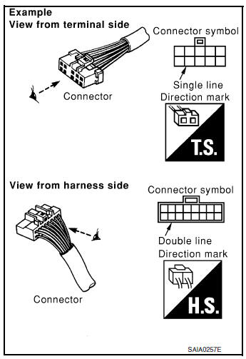
Most of connector symbols in wiring diagrams are shown from the terminal side.
- Connector symbols shown from the terminal side are enclosed by a single line and followed by the direction mark.
- Connector symbols shown from the harness side are enclosed by a double line and followed by the direction mark.
- Certain systems and components, especially those related to
OBD, may use a new style slide-locking type harness connector.
For description and how to disconnect, refer to PG section, ÔÇťDescriptionÔÇŁ, ÔÇťHARNESS CONNECTORÔÇŁ.
- Male and female terminals Connector guides for male terminals are shown in black and female terminals in white in wiring diagrams.

 Sample/Wiring Diagram -Example-
Each section includes wiring diagrams.
Description
Number
Item
Description
1
Power supply
This means the power supply of fusible link or fuse.
...
Other materials:
Meter control switch signal circuit
Diagnosis Procedure
Regarding Wiring Diagram information, refer to MWI-32, "Wiring Diagram".
1.CHECK METER CONTROL SWITCH SIGNAL
Turn ignition switch ON.
Check voltage between the following terminals of the meter control
switch harness connector M3.
Is the ins ...
Basic inspection
DIAGNOSIS AND REPAIR WORKFLOW
Work Flow
DETAILED FLOW
1.COLLECT THE INFORMATION FROM THE CUSTOMER
Get the detailed information from the customer about the symptom (the
condition and the environment when
the incident/malfunction occurred) using the diagnosis worksheet.
>> GO TO 2.
2. ...
P0604 ECM
DTC Description
DTC DETECTION LOGIC
DTC No.
CONSULT screen terms
(Trouble diagnosis content)
DTC detecting condition
P0604
ECM
[Internal control module random access
memory (RAM) error]
Malfunction in the internal RAM of ECM.
POSSIBLE CAUSE
ECM
FAIL-SAF ...
