Nissan Rogue Service Manual: Meter control switch signal circuit
Diagnosis Procedure
Regarding Wiring Diagram information, refer to MWI-32, "Wiring Diagram".
1.CHECK METER CONTROL SWITCH SIGNAL
- Turn ignition switch ON.
- Check voltage between the following terminals of the meter control switch harness connector M3.
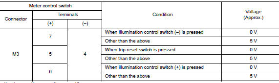
Is the inspection result normal? YES >> Inspection End.
NO >> GO TO 2.
2.CHECK METER CONTROL SWITCH HARNESS
- Turn ignition switch OFF.
- Disconnect combination meter harness connector M77 and meter control switch harness connector M3.
- Check continuity between combination meter harness connector M77 and meter control switch harness connector M3.
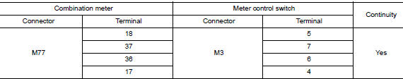
- Check continuity between combination meter harness connector and ground.
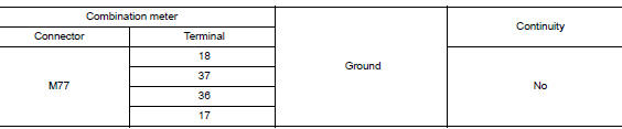
Is the inspection result normal? YES >> Inspection End.
NO >> Repair or replace harness or connectors.
Component Inspection
1.CHECK METER CONTROL SWITCH
- Turn ignition switch OFF.
- Disconnect meter control switch connector.
- Check meter control switch.
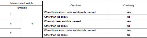
Is the inspection result normal? YES >> Inspection End.
NO >> Replace meter control switch. Refer to MWI-83, "Removal and Installation".
 Ambient sensor signal circuit
Description
It detects outside air temperature and converts it into a resistance value
which is then input into the combination
meter.
Diagnosis Procedure
Regarding Wiring Diagram information, r ...
 Steering switch
Description
When one of the steering switches is pushed, the resistance in the steering
switch changes the signal to
identify which button is controlling the information display.
Diagnosis Proced ...
Other materials:
Basic inspection
DIAGNOSIS AND REPAIR WORKFLOW
Work Flow
OVERALL SEQUENCE
DETAILED FLOW
1. GET INFORMATION FOR SYMPTOM
Get the detailed information from the customer about the symptom (the
condition and the environment when
the incident/malfunction occurred).
>> GO TO 2.
2. CHECK DTC
...
Preparation
Special Service Tool
The actual shape of the tools may differ from those illustrated here.
Tool number
(TechMate No.)
Tool name
Description
—
(J-46534)
Trim Tool Set
Removing trim components
Commercial Service Tools
Tool name
...
P060A ECM
DTC Description
DTC DETECTION LOGIC
DTC No.
CONSULT screen terms
(Trouble diagnosis content)
DTC detecting condition
P060A
CONTROL MODULE
(Internal control module monitoring processor
performance)
ECM internal monitoring processor is malfunctioning.
POSSI ...
