Nissan Rogue Service Manual: Steering switch
Description
When one of the steering switches is pushed, the resistance in the steering switch changes the signal to identify which button is controlling the information display.
Diagnosis Procedure
Regarding Wiring Diagram information, refer to MWI-32, "Wiring Diagram".
1.CHECK STEERING SWITCH CIRCUIT
- Turn ignition switch OFF.
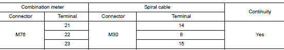
- Disconnect combination meter harness connector M76 and spiral cable harness connector M30.
- Check continuity between combination meter harness connector M76 and spiral cable harness connector M30.
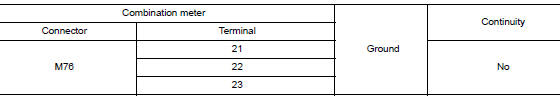
- Check continuity between combination meter harness connector M76 and ground.
Is the inspection result normal? YES >> Inspection End.
NO >> Repair or replace harness or connector.
Component Inspection
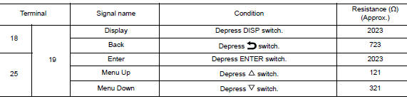
1.CHECK STEERING SWITCH RESISTANCE
Check resistance between the following steering switch terminals.
Is the inspection result normal? YES >> GO TO 2.
NO >> Replace steering wheel switch. Refer to AV-65, "Removal and Installation".
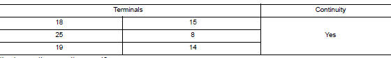
2.CHECK SPIRAL CABLE
Check continuity between the following spiral cable terminals.
Is the inspection result normal? YES >> Inspection End.
NO >> Replace spiral cable. Refer to SR-15, "Removal and Installation".
 Meter control switch signal circuit
Diagnosis Procedure
Regarding Wiring Diagram information, refer to MWI-32, "Wiring Diagram".
1.CHECK METER CONTROL SWITCH SIGNAL
Turn ignition switch ON.
Check voltage be ...
 Washer level switch signal circuit
Description
Transmits the washer fluid level switch signal to the combination meter.
Diagnosis Procedure
Regarding Wiring Diagram information, refer to MWI-32, "Wiring Diagram".
1.CHECK ...
Other materials:
Service data and specifications (SDS)
Oil Pressure
*: Engine oil temperature at 80°C (176°F)
Oil Pump
Relief Valve
Oil Capacity
...
P0127 IAT sensor
DTC Description
DTC DETECTION LOGIC
DTC No.
CONSULT screen terms
(Trouble diagnosis content)
DTC detecting condition
P0127
IAT SENSOR-B1
(Intake air temperature too high)
Rationally incorrect voltage from the sensor is sent to ECM,
compared with
the voltage ...
Driver side door mirror defogger
Description
Heats the heating wire with the power supply from the rear window defogger
relay to prevent the door mirror
from fogging up.
Component Function Check
1. CHECK DOOR MIRROR DEFOGGER LH
Check that heating wire of door mirror defogger LH is heated when turning the
rear window defogg ...
