Nissan Rogue Service Manual: Washer level switch signal circuit
Description
Transmits the washer fluid level switch signal to the combination meter.
Diagnosis Procedure
Regarding Wiring Diagram information, refer to MWI-32, "Wiring Diagram".
1.CHECK WASHER FLUID LEVEL SWITCH SIGNAL CIRCUIT
- Turn ignition switch OFF.
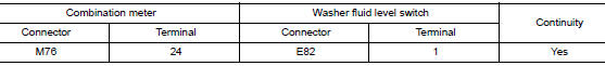
- Disconnect combination meter harness connector M76 and washer fluid level switch harness connector E82.
- Check continuity between combination meter harness connector M76 and washer fluid level switch harness connector E82.
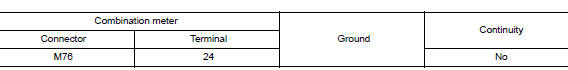
- Check continuity between combination meter harness connector and ground.
Is the inspection result normal? YES >> GO TO 2.
NO >> Repair or replace harness or connector.
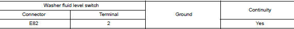
2.CHECK WASHER FLUID LEVEL SWITCH GROUND CIRCUIT
Check continuity between washer fluid level switch connector and ground.
Is the inspection result normal? YES >> Inspection End.
NO >> Repair or replace harness or connector.
Component Inspection
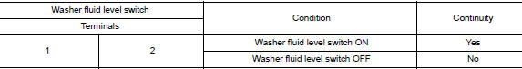
1.CHECK WASHER FLUID LEVEL SWITCH
- Turn ignition switch OFF.
- Disconnect washer fluid level switch connector.
- Check washer fluid level switch.
Is the inspection result normal?
YES >> Inspection End.
NO >> Replace washer fluid level switch. Refer to WW-58, "Removal and Installation".
 Steering switch
Description
When one of the steering switches is pushed, the resistance in the steering
switch changes the signal to
identify which button is controlling the information display.
Diagnosis Proced ...

Other materials:
Ignition signal
Component Function Check
1.INSPECTION START
Turn ignition switch OFF, and restart engine.
Does the engine start?
YES-1 >> With CONSULT: GO TO 2.
YES-2 >> Without CONSULT: GO TO 3.
NO >> Proceed to EC-470, "Diagnosis Procedure".
2.CHECK IGNITION SIGNAL FUNCTIO ...
Tire labeling
Example
Federal law requires tire manufacturers to
place standardized information on the
sidewall of all tires. This information identifies
and describes the fundamental
characteristics of the tire and also provides
the tire identification number (TIN)
for safety standard certification. The ...
C1105, C1106, C1107, C1108 wheel sensor
DTC Logic
DTC DETECTION LOGIC
DTC
Display Item
Malfunction detected condition
Possible causes
C1105
RR RH SENSOR-2
When distance between rear wheel sensor RH and
rear wheel sensor RH rotor is large.
When installation of rear whe ...
