Nissan Rogue Service Manual: Ignition signal
Component Function Check
1.INSPECTION START
Turn ignition switch OFF, and restart engine.
Does the engine start? YES-1 >> With CONSULT: GO TO 2.
YES-2 >> Without CONSULT: GO TO 3.
NO >> Proceed to EC-470, "Diagnosis Procedure".
2.CHECK IGNITION SIGNAL FUNCTION
 With CONSULT
- Perform “POWER BALANCE” in “ACTIVE TEST” mode with CONSULT.
- Check that each circuit produces a momentary engine speed drop.
Is the inspection result normal? YES >> INSPECTION END
NO >> Proceed to EC-470, "Diagnosis Procedure".
3.CHECK IGNITION SIGNAL FUNCTION
 Without CONSULT
- Let engine idle.
- Read the voltage signal between ECM harness connector terminals with an oscilloscope.
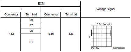
NOTE: The pulse cycle changes depending on rpm at idle. Is the inspection result normal? YES >> INSPECTION END
NO >> Proceed to EC-470, "Diagnosis Procedure".
Diagnosis Procedure
1.CHECK ECM POWER SUPPLY
- Turn ignition switch OFF, wait at least 10 seconds and then turn it ON.
- Check the voltage between ECM harness connector terminals.
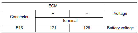
Is the inspection result normal? YES >> GO TO 2.
NO >> Refer to EC-165, "Diagnosis Procedure".
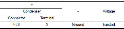
2.CHECK CONDENSER POWER SUPPLY
- Turn ignition switch OFF.
- Disconnect condenser harness connector.
- Turn ignition switch ON.
- Check the voltage between condenser harness connector and ground.
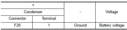
Is the inspection result normal? YES >> GO TO 4.
NO >> GO TO 3.
3.CHECK CONDENSER POWER SUPPLY CIRCUIT
- Turn ignition switch OFF.
- Disconnect IPDM E/R harness connector.
- Check the continuity between IPDM E/R harness connector and condenser harness connector.
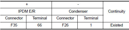
Also check harness for short to ground and to power.
Is the inspection result normal? YES >> Refer to EC-165, "Diagnosis Procedure".
NO >> Repair open circuit, short to ground or short to power in harness or connectors.
4.CHECK CONDENSER GROUND CIRCUIT
- Turn ignition switch OFF.
- Check the continuity between condenser harness connector and ground.
- Also check harness for short to power.
Is the inspection result normal? YES >> GO TO 5.
NO >> Repair open circuit or short to power in harness or connectors.
5.CHECK CONDENSER
Check condenser. Refer to EC-474, "Component Inspection (Condenser)" Is the inspection result normal? YES >> GO TO 6.
NO >> Replace condenser.
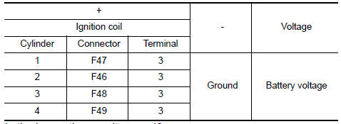
6.CHECK IGNITION COIL POWER SUPPLY
- Reconnect all harness connectors disconnected.
- Disconnect ignition coil harness connector.
- Turn ignition switch ON.
- Check the voltage between ignition coil harness connector and ground.
Is the inspection result normal? YES >> GO TO 7.
NO >> Repair or replace harness or connectors.
7.CHECK IGNITION COIL GROUND CIRCUIT
- Turn ignition switch OFF.
- Check the continuity between ignition coil harness connector and ground.
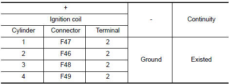
- Also check harness for short to power.
Is the inspection result normal? YES >> GO TO 8.
NO >> Repair open circuit or short to power in harness or connectors.
8.CHECK IGNITION COIL OUTPUT SIGNAL CIRCUIT
- Disconnect ECM harness connector.
- Check the continuity between ignition coil harness connector and ECM harness connector.
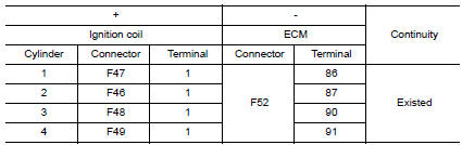
- Also check harness for short to ground and to power.
Is the inspection result normal? YES >> GO TO 9.
NO >> Repair open circuit, short to ground or short to power in harness or connectors.
9.CHECK IGNITION COIL WITH POWER TRANSISTOR
Check ignition coil with power transistor. Refer to EC-473, "Component Inspection (Ignition Coil with Power Transistor)".
Is the inspection result normal? YES >> Check intermittent incident. Refer to GI-41, "Intermittent Incident".
NO >> Replace malfunctioning ignition coil with power transistor. Refer to EM-36, "Removal and Installation".
Component Inspection (Ignition Coil with Power Transistor)
1.CHECK IGNITION COIL WITH POWER TRANSISTOR-1
- Turn ignition switch OFF.
- Disconnect ignition coil harness connector.
- Check resistance between ignition coil terminals as per the following.
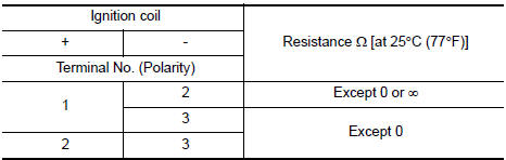
Is the inspection result normal? YES >> GO TO 2.
NO >> Replace malfunctioning ignition coil with power transistor. Refer to EM-36, "Removal and Installation".
2.CHECK IGNITION COIL WITH POWER TRANSISTOR-2
CAUTION: Perform the following procedure in a place with no combustible objects and good ventilation.
- Turn ignition switch OFF.
- Reconnect all harness connectors disconnected.
- Remove fuel pump fuse in IPDM E/R to release fuel pressure.
NOTE: Do not use CONSULT to release fuel pressure, or fuel pressure applies again during the following procedure.
- Start engine.
- After engine stalls, crank it 2 or 3 times to release all fuel pressure.
- Turn ignition switch OFF.
- Remove all ignition coil harness connectors to avoid the electrical discharge from the ignition coils.
- Remove ignition coil and spark plug of the cylinder to be checked.
- Crank engine for 5 seconds or more to remove combustion gas in the cylinder.
- Connect spark plug and harness connector to ignition coil.
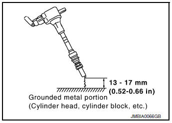
- Fix ignition coil using a rope etc. with gap of 13 - 17 mm (0.52 - 0.66 in) between the edge of the spark plug and grounded metal portion as shown in the figure.
- Crank engine for approximately 3 seconds, and check whether spark is generated between the spark plug and the grounded metal portion.
Spark should be generated.
CAUTION:
- During the operation, always stay 0.5 m (19.7 in) or more away from the spark plug and the ignition coil. Be careful not to get an electrical shock while checking, because the electrical discharge voltage becomes 20 kV or more.
- It might cause to damage the ignition coil if the gap of more than 17 mm (0.66 in) is taken.
NOTE: When the gap is less than 13 mm (0.52 in), the spark might be generated even if the coil is malfunctioning. Is the inspection result normal? YES >> INSPECTION END
NO >> Replace malfunctioning ignition coil with power transistor. Refer to EM-36, "Removal and Installation".
Component Inspection (Condenser)
1.CHECK CONDENSER
- Turn ignition switch OFF.
- Disconnect condenser harness connector.
- Check resistance between condenser terminals as per the following.
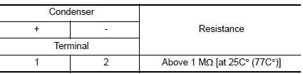
Is the inspection result normal? YES >> INSPECTION END
NO >> Replace condenser.
 Fuel pump
Description
Sensor
Input signal to ECM
ECM Function
Actuator
Crankshaft position sensor (POS)
Camshaft position sensor (PHASE)
Engine speed*
Fuel pump control
Fue ...
 Information display (ASCD)
Component Function Check
1.CHECK INFORMATION DISPLAY
Start engine.
Press ASCD MAIN switch on ASCD steering switch.
Drive the vehicle at more than 40 km/h (25 MPH).
CAUTION ...
Other materials:
Removal and installation
NATS ANTENNA AMP.
Exploded View
Instrument finisher B
Push button ignition switch
NATS antenna amp.
Pawl
Removal and Installation
REMOVAL
Remove the instrument finisher B. Refer to IP-16, "INSTRUMENT
FINISHER B : Removal and Installation".
Release ...
System description
COMPONENT PARTS
Component Parts Location
Right rear wheel area
Instrument panel
Engine compartment
Left side of instrument panel (view
with trim panel removed)
No.
Part
Function
1
Optical sensor
Refer to EXL-10, "Optical Sensor" ...
Diagnosis system (BCM) (without intelligent key system)
COMMON ITEM
COMMON ITEM : CONSULT Function (BCM - COMMON ITEM)
APPLICATION ITEM
CONSULT performs the following functions via CAN communication with BCM.
Direct Diagnostic Mode
Description
Ecu Identification
The BCM part number is displayed.
Self Diagnostic ...
