Nissan Rogue Service Manual: Removal and installation
NATS ANTENNA AMP.
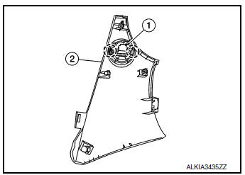
Exploded View
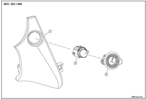
- Instrument finisher B
- Push button ignition switch
- NATS antenna amp.
 Pawl
Pawl
Removal and Installation
REMOVAL
- Remove the instrument finisher B. Refer to IP-16, "INSTRUMENT FINISHER B : Removal and Installation".
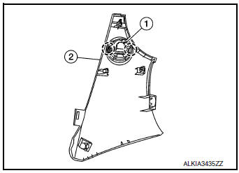
- Release pawls and remove NATS antenna amp. (1) from instrument finisher B (2).
: Pawl
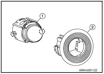
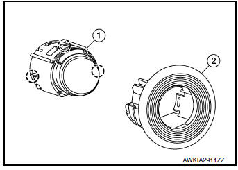
- Release pawls and remove NATS antenna amp. (2) from push
button ignition switch (1).: Pawl
INSTALLATION
Installation is in the reverse order of removal.
PUSH-BUTTON IGNITION SWITCH
Exploded View
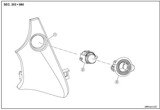
- Instrument finisher B
- Push button ignition switch
- NATS antenna amp.
Pawl
Removal and Installation
REMOVAL
- Remove the instrument finisher B. Refer to IP-16, "INSTRUMENT FINISHER B : Removal and Installation".
- Release pawls and remove NATS antenna amp. (1) from instrument
finisher B (2).: Pawl
- Release pawls and remove NATS antenna amp. (2) from push
button ignition switch (1).: Pawl
INSTALLATION
Installation is in the reverse order of removal.
 Symptom diagnosis
ENGINE DOES NOT START WHEN INTELLIGENT KEY IS INSIDE OF VEHICLE
Description
Engine does not start when push-button ignition switch is pressed while
carrying Intelligent Key.
NOTE:
Check ...

Other materials:
Parking brake system
Inspection and Adjustment
INSPECTION
Pedal Stroke
Operate the parking brake pedal with a force of 196 N (20.0 kg-f,
44.1 lb-f). Check that the pedal stroke is
within the specified number of notches. (Check it by listening to the clicks
of the ratchet.)
Number of notches : Refe ...
P0461 fuel level sensor
DTC Description
DTC DETECTION LOGIC
Driving long distances naturally affect fuel gauge level.
This diagnosis detects the fuel gauge malfunction of the gauge not moving even
after a long distance has
been driven.
DTC No.
CONSULT screen terms
(Trouble diagnosis content)
DTC de ...
Basic inspection
DIAGNOSIS AND REPAIR WORKFLOW
Work Flow
OVERALL SEQUENCE
DETAILED FLOW
1.GET INFORMATION FOR SYMPTOM
Get the detailed information from the customer about the symptom (the
condition and the environment when
the incident/malfunction occurred).
>> GO TO 2.
2.CHECK DTC
Ch ...
