Nissan Rogue Service Manual: Removal and installation
HOOD
Exploded View
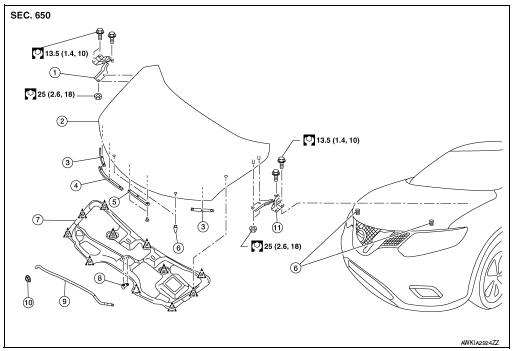
- Hood hinge (RH)
- Hood
- Hood side seal
- Hood front seal
- Hood center seal
- Bumper rubber
- Hood insulator
- Hood rod clamp
- Hood support rod
- Hood rod grommet
- Hood hinge (LH)
HOOD ASSEMBLY
HOOD ASSEMBLY : Removal and Installation
CAUTION:
- Use two people when removing or installing hood assembly due to its heavy weight.
- Use protective tape or shop cloths to protect surrounding components from damage during removal and installation of hood assembly.
REMOVAL
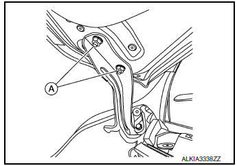
- Support the hood assembly using a suitable tool.
WARNING: Bodily injury may occur if hood assembly is not supported properly when removing hood assembly.
- Remove hood hinge to hood nuts (A) and hood assembly.
NOTE: RH side shown; LH similar.
INSTALLATION
Installation is in the reverse order of removal.
CAUTION:
- Before installing the hood hinge, apply anticorrosive agent onto the surface of the vehicle.
- After installation, perform the hood assembly adjustment procedure. Refer to DLK-234, "HOOD ASSEMBLY : Adjustment".
HOOD ASSEMBLY : Adjustment
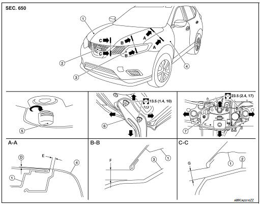
- Hood assembly
- Front grille
- Front combination lamp
- Fender
- Bumper rubber
- Hood hinge
- Hood lock
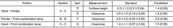
Check the clearance and the surface height between hood and each part by visual inspection and tactile feel.
If the clearance and the surface height are out of specification, adjust them according to the adjustment procedures.
HEIGHT ADJUSTMENT
- Loosen the hood lock assembly bolts.
- Adjust the surface height of hood assembly to front grille and front fender according to the specified values by rotating hood bumper rubber.
- Temporarily tighten hood lock assembly bolts.
- Adjust (A) and (B) as shown to the following value with hood's own weight by dropping it from approximately 200 mm (7.87 in) height or by pressing hood lightly [approximately 29 N (3.0 kg, 6.5 lb)].
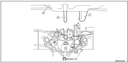
- Secondary striker
- Primary striker
- Hood assembly
- 20 mm (0.79 in)
- 6.8 mm (0.27 in)
- After adjustment, tighten hood hinge nuts and bolts to the specified torque.
CAUTION:
- Check hood hinge rotating part for poor lubrication. If necessary, apply a suitable multi-purpose grease.
- After adjusting, apply touch-up paint (body color) to the head of hood hinge bolts and nuts.
CLEARANCE ADJUSTMENT
- Loosen hood hinge nuts and bolts.
- Loosen the hood lock assembly bolts.
- Adjust the hood assembly so the clearance measurements are within specifications.
- Tighten the hood hinge nuts and bolts to specified torque.
- Tighten the hood lock assembly bolts to specified torque.
HOOD HINGE
HOOD HINGE : Removal and Installation
REMOVAL
- Remove hood assembly. Refer to DLK-233, "HOOD ASSEMBLY : Removal and Installation".
- Remove front fender. Refer to DLK-238, "Removal and Installation".
- Remove hood hinge bolts, and then remove hood hinge.
INSTALLATION
Installation is in the reverse order of removal.
CAUTION:
- Before installing the hood hinge, apply anticorrosive agent onto the surface of the vehicle.
- After installation, perform hood assembly adjustment procedure. Refer to DLK-234, "HOOD ASSEMBLY : Adjustment".
RADIATOR CORE SUPPORT
Exploded View
- Radiator core upper support
- Secondary latch bracket
- Radiator core lower support
Removal and Installation
CAUTION: When removing radiator core support upper, be careful not to damage the painted surface.
REMOVAL
Radiator Core Upper Support
- Remove front combination lamp (LH). Refer to EXL-119, "Removal and Installation".
- Remove front air duct. Refer to EM-24, "Exploded View".
- Remove hood lock. Refer to DLK-253, "HOOD LOCK : Removal and Installation".
- Remove secondary latch. Refer to DLK-254, "SECONDARY LATCH : Removal and Installation".
- Remove crash zone sensor. Refer to SR-22, "Removal and Installation".
- Remove bolts and radiator core upper support.
Radiator Core Lower Support
- Remove front bumper fascia. Refer to EXT-17, "Removal and Installation".
- Support the radiator using a suitable tool.
- Remove bolts and radiator core lower support.
INSTALLATION
Installation is in the reverse order of removal.
CAUTION: Tighten bolts to specified torque. Refer to DLK-237, "Exploded View".
FRONT FENDER
Exploded View
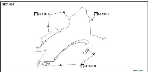
- Front fender
Removal and Installation
CAUTION: Use a shop cloths to protect the body from being damaged during removal and installation.
REMOVAL
- Remove front bumper fascia. Refer to EXT-17, "Removal and Installation".
- Remove front combination lamp. Refer to EXL-119, "Removal and Installation" (HALOGEN HEADLAMP) or EXL-268, "Removal and Installation". (LED HEADLAMP).
- Remove center mudguard. Refer to EXT-35, "Removal and Installation - Center Mudguard".
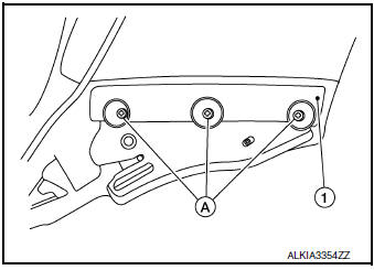
- Remove screws (A) and front fender bracket (1).
- Remove bolts and front fender.
CAUTION: Use care when removing the front fender. The front fender baffle foam adheres the front fender to the body side outer. Carefully release the baffle foam or damage to the front fender may occur.
INSTALLATION
Installation is in the reverse order of removal.
CAUTION:
- After installation apply touch up paint (body color) to the head of front fender bolts.
- After installation, adjust the following components as necessary:
- Hood assembly: Refer to DLK-234, "HOOD ASSEMBLY : Adjustment".
- Front door: Refer to DLK-241, "DOOR ASSEMBLY : Adjustment".
- Tighten bolts to specification. Refer to DLK-238, "Exploded View".
FRONT DOOR
Exploded View
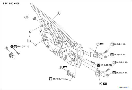
- Front door panel
- Grommet
- Bumper rubber
- Door striker
- Door check link
- Front door lower hinge
- Front door upper hinge
DOOR ASSEMBLY
DOOR ASSEMBLY : Removal and Installation
CAUTION:
- Use two people when removing or installing the front door due to its heavy weight.
- When removing and installing front door assembly, support front door with a suitable tool.
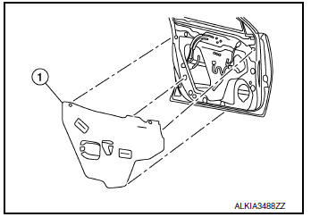
REMOVAL
- Remove front door finisher. Refer to INT-15, "Removal and Installation".
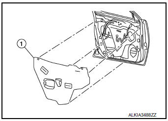
- Remove front door vapor barrier (1).
NOTE: LH side shown; RH similar.
- Disconnect the harness connectors from the front door.
- Remove front door harness grommet, then harness from the front door.
- Remove front door check link bolt (body side).
- Remove front door hinge nuts (door side) and front door assembly.
INSTALLATION
Installation is in the reverse order of removal.
CAUTION:
- Tighten nuts/bolts to specified torque. Refer to DLK-240, "Exploded View".
- Apply anticorrosive agent where necessary.
- After installation, check front door open/close and lock/unlock operation.
- After installation, perform the front door adjustment procedure. Refer to DLK-241, "DOOR ASSEMBLY : Adjustment".
DOOR ASSEMBLY : Adjustment
ADJUSTMENT
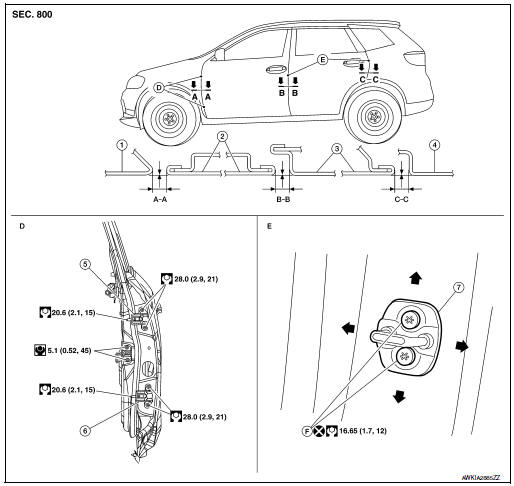
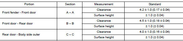
- Front fender
- Front door
- Rear door
- Body side outer
- Front door upper hinge
- Front door lower hinge
- Door striker
- Front door striker bolts
Check the clearance and surface height between front door and each part by visual inspection and tactile feel.
If the clearance and the surface height are out of specification, adjust them according to the adjustment procedure.
- Remove front fender. Refer to DLK-238, "Removal and Installation".
- Loosen front door hinge nuts (door side).
- Adjust the surface height of front door according to the specifications provided.
- Temporarily tighten front door hinge nuts (door side).
- Loosen front door hinge bolts (body side).
- Raise front door at rear end to adjust clearance of the front door according to the specifications provided.
- After adjustment tighten bolts and nuts to the specified torque.
CAUTION:
- Check door hinge rotating point for poor lubrication. If necessary, apply a suitable multi-purpose grease.
- After adjusting, apply touch-up paint (body color) to the head of front door hinge bolts and nuts.
- Install front fender. Refer to refer to DLK-238, "Removal and Installation".
DOOR STRIKER
DOOR STRIKER : Removal and Installation
REMOVAL
Remove bolts and front door striker.
INSTALLATION
Installation is in the reverse order of removal.
CAUTION:
- Do not reuse front door striker bolts.
- After installation, check front door open/close operation. If
necessary, adjust the front door striker.
Refer to DLK-242, "DOOR STRIKER : Adjustment".
- Tighten bolts to specified torque. Refer to DLK-240, "Exploded View".
DOOR STRIKER : Adjustment
DOOR STRIKER ADJUSTMENT
- Loosen door striker bolts
- Adjust door striker so that it becomes parallel with front door lock insertion direction.
- Tighten door striker bolts to specification. Refer to DLK-240, "Exploded View".
DOOR HINGE
DOOR HINGE : Removal and Installation
REMOVAL
- Remove front fender. Refer to DLK-238, "Removal and Installation".
- Remove front door assembly. Refer to DLK-240, "DOOR ASSEMBLY : Removal and Installation".
- Remove front door hinge bolts (body side) and front door hinge.
INSTALLATION
Installation is in the reverse order of removal.
CAUTION:
- Tighten nuts/bolts to specified torque. Refer to DLK-240, "Exploded View".
- Apply anticorrosive agent to the hinge mating surface.
- After installation, check front door open/close and lock/unlock operation.
- Check door hinge rotating point for poor lubrication. If necessary, apply a suitable multi-purpose grease.
- After installation, perform the front door adjustment procedure. Refer to DLK-241, "DOOR ASSEMBLY : Adjustment".
DOOR CHECK LINK
DOOR CHECK LINK : Removal and Installation
REMOVAL
- Fully close the front door window.
- Remove front door speaker. Refer to AV-67, "Removal and Installation" (DISPLAY AUDIO), AV-213, "Removal and Installation" (NAVIGATION WITHOUT BOSE) or AV-381, "Removal and Installation" (NAVIGATION WITH BOSE).
- Remove door check link bolt (body side).
- Remove door check link bolts (door side).
- Remove door check link through the hole in door assembly.
INSTALLATION
Installation is in the reverse order of removal.
CAUTION:
- Tighten nuts/bolts to specified torque. Refer to DLK-240, "Exploded View".
- After installation, check front door open/close and lock/unlock operation.
- Check door check link rotating point for poor lubrication. If necessary, apply a suitable multi-purpose grease.
REAR DOOR
Exploded View
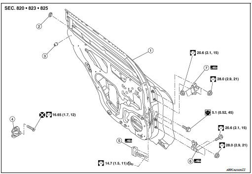
- Rear door panel
- Grommet
- Bumper rubber
- Door striker
- Door check link
- Rear door lower hinge
- Rear door upper hinge
DOOR ASSEMBLY
DOOR ASSEMBLY : Removal and Installation
CAUTION:
- Use two people when removing or installing the rear door due to its heavy weight.
- When removing and installing rear door assembly, support rear door using a suitable tool.
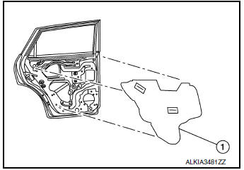
REMOVAL
- Remove rear door finisher. Refer to DLK-244, "DOOR ASSEMBLY : Removal and Installation".
- Remove rear door vapor barrier (1).
NOTE: LH side shown; RH similar.
- Disconnect the harness connectors from rear door.
- Remove harness grommet from rear door, then pull out rear door harness from the rear door.
- Remove rear door check link bolt (body side).
- Remove rear door hinge nuts (door side) and rear door assembly.
INSTALLATION
Installation is in the reverse order of removal.
CAUTION:
- Tighten nuts/bolts to specification. Refer to DLK-244, "Exploded View".
- Apply anticorrosive agent where necessary.
- After installation, check rear door open/close and lock/unlock operation.
- After installation, perform the rear door adjustment procedure. Refer to DLK-245, "DOOR ASSEMBLY : Adjustment".
DOOR ASSEMBLY : Adjustment
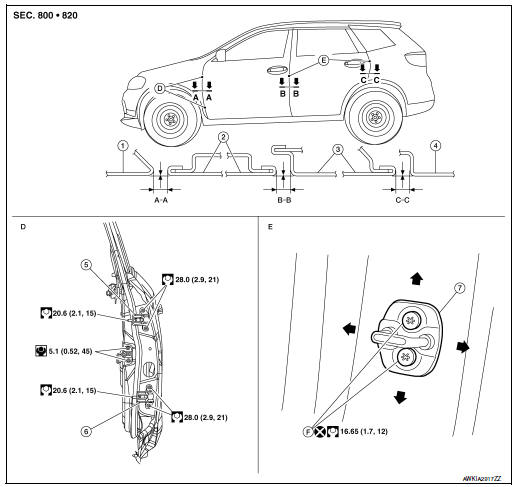
- Front fender
- Front door
- Rear door
- Body side outer
- Door striker
- Rear door upper hinge
- Rear door lower hinge
- Door striker bolts
Check the clearance and surface height between rear door and each part by visual inspection and tactile feel.
If the clearance and the surface height are out of specification, adjust them according to the adjustment procedures.
- Remove center pillar lower finisher. Refer to INT-22, "CENTER PILLAR LOWER FINISHER : Removal and Installation".
- Loosen rear door hinge nuts (door side).
- Adjust the surface height of rear door according to specifications provided.
- Temporarily tighten rear door hinge nuts (door side).
- Loosen rear door hinge nuts and bolts (body side).
- Raise rear door at rear end to adjust clearance of rear door according to the specifications provided.
- After adjustment tighten bolts and nuts to the specified torque.
CAUTION:
- Check rear door hinge rotating point for poor lubrication. If necessary, apply a suitable multi-purpose grease.
- After adjusting, apply touch-up paint (body color) to the head of rear door hinge bolts and nuts.
- Install center pillar lower finisher. Refer to INT-22, "CENTER PILLAR LOWER FINISHER : Removal and Installation".
DOOR STRIKER
DOOR STRIKER : Removal and Installation
REMOVAL
Remove bolts and rear door striker.
INSTALLATION
Installation is in the reverse order of removal.
CAUTION:
- Do not reuse rear door striker bolts.
- Tighten bolts to specification. Refer to DLK-244, "Exploded View".
- After installation, check rear door open/close operation. If necessary, adjust the door striker. Refer to DLK-246, "DOOR STRIKER : Adjustment".
DOOR STRIKER : Adjustment
DOOR STRIKER ADJUSTMENT
- Loosen door striker bolts
- Adjust door striker so that it becomes parallel with front door lock insertion direction.
- Tighten door striker bolts to specification. Refer to DLK-244, "Exploded View".
DOOR HINGE
DOOR HINGE : Removal and Installation
REMOVAL
- Remove rear door assembly. Refer to DLK-244, "DOOR ASSEMBLY : Removal and Installation".
- Remove center pillar lower finisher (rear door lower hinge only). Refer to INT-22, "CENTER PILLAR LOWER FINISHER : Removal and Installation".
- Remove rear door hinge bolts and nuts and rear door hinge.
INSTALLATION
Installation is in the reverse order of removal.
CAUTION:
- Tighten nuts/bolts to specification. Refer to DLK-244, "Exploded View".
- Apply anticorrosive agent onto the hinge mating surface.
- After installation, check rear door open/close and lock/unlock operation.
- After installation, perform the rear door adjustment procedure. Refer to DLK-245, "DOOR ASSEMBLY : Adjustment".
DOOR CHECK LINK
DOOR CHECK LINK : Removal and Installation
REMOVAL
- Fully close the rear door window.
- Remove rear door speaker. Refer to AV-68, "Removal and Installation" (DISPLAY AUDIO), AV-214, "Removal and Installation" (NAVIGATION WITHOUT BOSE) or AV-383, "Removal and Installation" (NAVIGATION WITH BOSE).
- Remove rear door check link bolt (body side).
- Remove rear door check link bolts (door side).
- Remove rear door check link through the hole in rear door panel.
INSTALLATION
Installation is in the reverse order of removal.
CAUTION:
- Tighten bolts to specification. Refer to DLK-244, "Exploded View".
- After installation, check rear door open/close and lock/unlock operation.
- Check rear door check link rotating point for poor lubrication. If necessary, apply a suitable multipurpose grease.
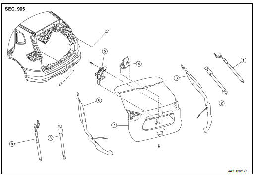
BACK DOOR
Exploded View
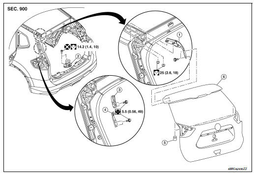
- Back door hinge
- Back door striker
- Spindle unit hinge (with automatic back door)
- Back door stay hinge
- Bumper rubber
- Back door
BACK DOOR ASSEMBLY
BACK DOOR ASSEMBLY : Removal and Installation
CAUTION:
- Use two people when removing or installing the back door due to its heavy weight.
- Use shop cloths to protect surrounding components from damage during removal and installation of back door.
REMOVAL
- Support the back door assembly using a suitable tool.
WARNING: Bodily injury may occur if back door assembly is not supported properly when removing the back door spindle unit.
- Remove spindle units (LH/RH) or back door stays (LH/RH). Refer to DLK-263, "SPINDLE UNIT : Removal and Installation" (WITH AUTOMATIC BACK DOOR) or DLK-264, "BACK DOOR STAY : Removal and Installation" (WITHOUT AUTOMATIC BACK DOOR).
- Remove roof side moldings (LH/RH). Refer to EXT-39, "Removal and Installation".
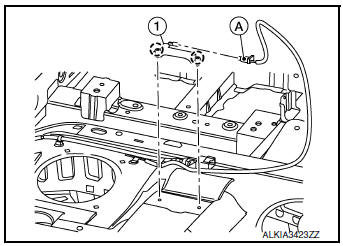
- Disconnect harness connectors (A) from back door.
- Remove back door harness grommet, then pull harness from the back door.
- Disconnect washer tube.
- Remove washer tube grommet and washer tube from the back door.
- Remove back door hinge bolts (door side) and back door assembly.
INSTALLATION
Installation is in the reverse order of removal.
CAUTION:
- Tighten bolts to specification. Refer to DLK-248, "Exploded View".
- Apply anticorrosive agent onto the surface between hinge and door side.
- When reusing stud ball, always apply locking sealant before installing stud ball to back door.
- After installation, perform the back door assembly adjustment procedure. Refer to DLK-250, "BACK DOOR ASSEMBLY : Adjustment".
- Perform calibration of automatic back door position information. Refer to DLK-103, "Work Procedure".
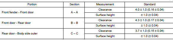
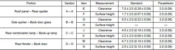
BACK DOOR ASSEMBLY : Adjustment

- Back door assembly
- Roof panel
- Rear spoiler
- Back door glass
- Rear combination lamp
- Back-up lamp
- Rear fender
- Side spoiler
Check the clearance and the surface height between back door and each part by visual inspection and tactile feel. If the clearance and the surface height are out of specification, adjust them according to the adjustment procedure.
- Loosen back door hinge nuts (door side).
- Lift up back door approximately 100 – 150 mm (3.94 – 5.91 in) height then close it lightly and check that it is engaged firmly with back door closed.
- Check the clearance and surface height according to the specifications provided.
- Tighten back door hinge nuts to specified torque.
CAUTION:
- After installation, check back door open/close, lock/unlock operation.
- Check back door hinge rotating point for poor lubrication. If necessary, apply a suitable multipurpose grease.
- After adjusting, apply touch-up paint (body color) to the head of rear door hinge bolts and nuts.
BACK DOOR STRIKER
BACK DOOR STRIKER : Removal and Installation
REMOVAL
- Release back door striker cover (1) pawls using a suitable tool
and remove.
 : Pawl
- Remove bolts and back door striker.
INSTALLATION
Installation is in the reverse order of removal.
CAUTION:
- Do not reuse back door striker bolts.
- Tighten bolts to specification. Refer to DLK-248, "Exploded View".
- After installation, check back door open/close operation. If necessary, adjust the door striker. Refer to DLK-251, "BACK DOOR STRIKER : Adjustment".
BACK DOOR STRIKER : Adjustment
DOOR STRIKER ADJUSTMENT
- Loosen door striker bolts
- Adjust door striker so that it becomes parallel with front door lock insertion direction.
- Tighten door striker bolts to specification. Refer to DLK-248, "Exploded View".
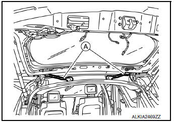
BACK DOOR HINGE
BACK DOOR HINGE : Removal and Installation
REMOVAL
- Remove back door assembly. Refer to DLK-248, "BACK DOOR ASSEMBLY : Removal and Installation".
- Partially remove the rear of the headlining. Refer to INT-30, "Removal and Installation".
- Remove nuts and back door hinge.
INSTALLATION
Installation is in the reverse order of removal.
CAUTION:
- Tighten nuts to specification. Refer to DLK-248, "Exploded View".
- Apply anticorrosive agent onto the surface between hinge and body side.
- After installation, perform the back door assembly adjustment procedure. Refer to DLK-250, "BACK DOOR ASSEMBLY : Adjustment".
BACK DOOR WEATHER-STRIP
BACK DOOR WEATHER-STRIP : Removal and Installation
REMOVAL
Carefully remove back door weather-strip from opening door joint.
INSTALLATION
- Beginning with upper section, align weather-strip mark with vehicle center position mark and install weather strip to the vehicle.
- For the lower section, align weather-strip seam with center of back door striker.
NOTE: Pull weather-strip gently to ensure that there are no loose sections.
HOOD LOCK
Exploded View
- Hood lock release handle
- Hood lock release cable
- Hood lock
- Secondary latch
- Clip
HOOD LOCK
HOOD LOCK : Removal and Installation
REMOVAL
- Disconnect hood lock release cable and secondary latch cable from hood lock.
- Remove bolts and hood lock.
INSTALLATION
Installation is in the reverse order of removal.
CAUTION:
- Tighten bolts to specified torque. Refer to DLK-253, "Exploded View".
- Check that hood lock release cable and secondary latch cable are properly engaged with hood lock.
- After installation, perform hood assembly adjustment procedure. Refer to DLK-234, "HOOD ASSEMBLY : Adjustment".
- After adjusting, perform hood lock inspection. Refer to DLK-253, "HOOD LOCK : Inspection".
HOOD LOCK : Inspection
NOTE: If the hood lock cable is bent or deformed, replace it.
- Check that secondary latch is properly engaged with secondary striker with hoods own weight.
- While operating hood lock release handle, carefully check that the front end of hood assembly is raised by approximately 20.0 mm (0.79 in). Also check that hood lock release handle returns to the original position.
- Check that hood lock release handle operates at 49 N (5.0 kg-m, 11.0 ft-lb) or below.
- Install so that static closing force of hood is 315-490 N (32.1-50.0 kg–m, 70.8-110.2 ft–lb).
NOTE:
- Do not exert vertical force on right side and left side of hood lock.
- Do not press simultaneously on both sides.
- Check the hood lock lubrication condition. If necessary, apply a suitable multi-purpose grease to hood lock assembly.
SECONDARY LATCH
SECONDARY LATCH : Removal and Installation
REMOVAL
- Remove front grille. Refer to EXT-23, "Removal and Installation".
- Disconnect secondary latch cable from hood lock assembly.
- Remove bolts and secondary latch.
INSTALLATION
Installation is in the reverse order of removal.
CAUTION:
- Tighten bolts to specified torque. Refer to DLK-253, "Exploded View".
- Check that secondary latch cable is properly engaged with hood lock.
HOOD LOCK RELEASE CABLE
HOOD LOCK RELEASE CABLE : Removal and Installation
REMOVAL
- Remove fender protector (LH). Refer to EXT-28, "FENDER PROTECTOR : Removal and Installation".
- Remove front grille. Refer to EXT-23, "Removal and Installation".
- Disconnect hood lock release cable from hood lock release handle and hood lock.
- Release hood lock release cable clips using a suitable tool.
- Remove grommet on the lower dash and carefully pull the hood lock release cable into the passenger compartment.
CAUTION: While pulling, be careful not to damage (peel) the outside of hood lock release cable.
INSTALLATION
Installation is in the reverse order of removal.
CAUTION:
- Be careful not to bend cable too much, keep the radius 100 mm (3.94 in) or more.
- Check that cable is not offset from the positioning grommet, and apply the sealant to the grommet (at * mark) properly.
- Check that hood lock release cable is properly engaged with hood lock assembly.
- After installation, perform hood assembly adjustment procedure. Refer to DLK-234, "HOOD ASSEMBLY : Adjustment".
- After adjusting, perform hood lock inspection. Refer to DLK-253, "HOOD LOCK : Inspection".
HOOD LOCK RELEASE HANDLE
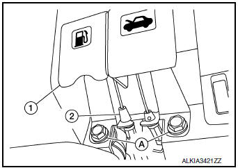
HOOD LOCK RELEASE HANDLE : Removal and Installation
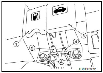
REMOVAL
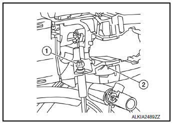
- Remove fuel filler lid/hood lock release handle bolts (A).
- Disconnect fuel filler lid release cable (2) from fuel filler lid release handle (1).
- Disconnect hood lock release cable (4) from hood lock release handle (3).
- Remove hood lock release handle.
INSTALLATION
Installation is in the reverse order of removal.
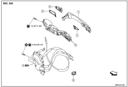
FRONT DOOR LOCK
Exploded View
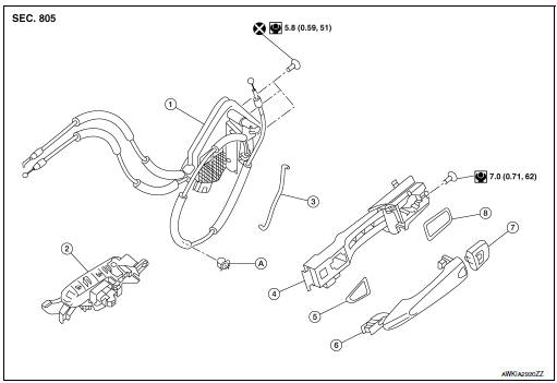
- Front door lock
- Inside handle
- Door key cylinder rod (LH only)
- Outside handle bracket
- Front gasket
- Outside handle
- Outside handle escutcheon / door key cylinder (LH only)
- Rear gasket
- Clip
DOOR LOCK
DOOR LOCK : Removal and Installation
REMOVAL
- Remove front door finisher. Refer to INT-15, "Removal and Installation".
- Remove vapor barrier.
- Remove front door lock bolts (A).
- Disconnect door key cylinder rod (LH only) (1) from front door lock (2) (LH only).
- Disconnect door lock cables from inside handle and outside handle..
- Disconnect the harness connector from the front door lock and remove.
INSTALLATION
Installation is in the reverse order of removal.
CAUTION:
- Do not reuse front door lock bolts.
- Tighten bolts to specification. Refer to DLK-256, "Exploded View".
- After installation, check door lock cables are properly engaged to inside handle and outside handle bracket.
- When installing door key cylinder rod (LH only), be sure to rotate door key cylinder rod holder until a click is felt.
- After installation, check door open/close and lock/unlock operation.
- Check door lock assembly for poor lubrication. If necessary apply a suitable multi-purpose grease.
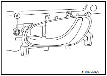
INSIDE HANDLE
INSIDE HANDLE : Removal and Installation
REMOVAL
- Remove front door finisher. Refer to INT-15, "Removal and Installation".
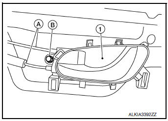
- Remove inside handle bolt (B).
- Disconnect the door lock cables (A) and remove inside handle (1).
INSTALLATION
Installation is in the reverse order of removal.
CAUTION:
- After installation, check door lock cables are properly engaged to inside handle.
- After installation, check door open/close and lock/unlock operation.
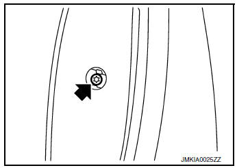
OUTSIDE HANDLE
OUTSIDE HANDLE : Removal and Installation
REMOVAL
- Fully close front door glass.
- Remove front door finisher. Refer to INT-15, "Removal and Installation".
- Remove front door vapor barrier (1).
NOTE: LH side shown; RH similar.
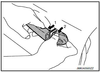
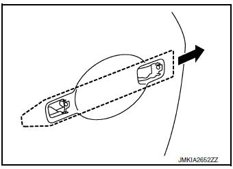
- Remove door side grommet (1), and remove bolt from grommet hole (2).

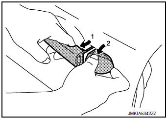
- Separate door key cylinder rod (LH only) (1) from door key cylinder assembly (LH only) (2).
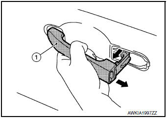
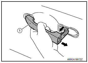
- While pulling (1) outside handle, remove (2) door key cylinder assembly (LH side) or outside handle escutcheon (RH side).
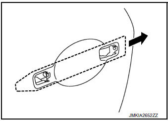
- While pulling outside handle (1), slide toward rear of vehicle to remove outside handle.
- Remove front gasket and rear gasket.
- Slide outside handle bracket toward rear of vehicle to remove.
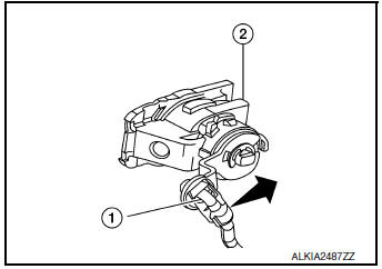
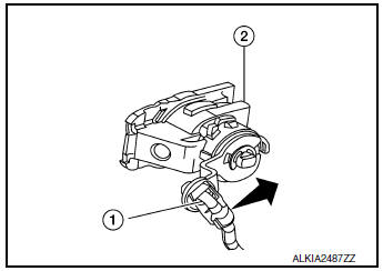
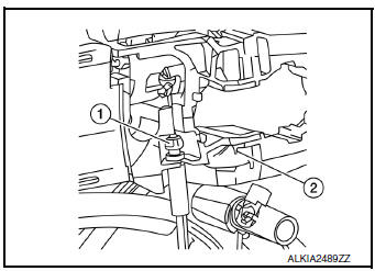
- Disconnect outside handle cable (1) from outside handle bracket (2) as shown.
INSTALLATION
Installation is in the reverse order of removal.
CAUTION:
- When installing door key cylinder rod (LH only), be sure to rotate door key cylinder rod holder until a click is felt.
- After installation, check door lock cable is properly engaged to outside handle bracket.
- After installation, check door open/close and lock/unlock operation.
REAR DOOR LOCK
Exploded View
- Outside handle
- Outside handle escutcheon
- Rear gasket
- Rear door lock
- Cable clip
- Outside handle bracket
- Front gasket
 Front
Front
DOOR LOCK
DOOR LOCK : Removal and Installation
REMOVAL
- Remove rear door finisher. Refer to INT-18, "Removal and Installation".
- Remove vapor barrier.
- Remove rear door lock bolts.
- Disconnect the door lock cables.
- Disconnect the harness connector from the rear door lock and remove.
INSTALLATION
Installation is in the reverse order of removal.
CAUTION:
- Do not reuse rear door lock bolts.
- Tighten bolts to specification. Refer to DLK-260, "Exploded View".
- After installation, check door lock cables are properly engaged to inside handle and outside handle.
- After installation, check door open/close and lock/unlock operation.
INSIDE HANDLE
INSIDE HANDLE : Removal and Installation
REMOVAL
- Remove rear door finisher. Refer to INT-18, "Removal and Installation".
- Remove inside handle bolt (A).
- Disconnect door lock cables from inside handle and remove.
INSTALLATION
Installation is in the reverse order of removal.
CAUTION:
- After installation, check door lock cables are properly engaged to inside handle.
- After installation, check door open/close and lock/unlock operation.
OUTSIDE HANDLE
OUTSIDE HANDLE : Removal and Installation
REMOVAL
- Fully close rear door glass.
- Remove rear door finisher. Refer to INT-18, "Removal and Installation".
- Remove rear door vapor barrier (1).
NOTE: LH side shown; RH similar.

- Remove door side grommet and bolt from grommet hole.
- While pulling (1) outside handle, remove (2) outside handle escutcheon.
- While pulling outside handle (1), slide toward rear of vehicle to remove outside handle.
- Remove front gasket and rear gasket.
- Slide outside handle bracket toward rear of vehicle to remove.
- Disconnect outside handle cable (1) from outside handle bracket (2) as shown.
INSTALLATION
Installation in the reverse order of removal.
CAUTION:
- After installation, check door lock cable is properly engaged to outside handle bracket.
- After installation, check door open/close and lock/unlock operation.
BACK DOOR LOCK
Exploded View
- Spindle unit (RH) (with automatic back door)
- Back door stay (RH)
- Back door touch sensor (RH) (with automatic back door)
- Back door lock
- Back door lock (with automatic back door)
- Back door touch sensor (LH) (with automatic back door)
- Back door
- Back door stay (LH)
- Spindle unit (LH) (with automatic back door)
DOOR LOCK
DOOR LOCK : Removal and Installation
REMOVAL
- Remove back door finisher. Refer to INT-38, "Removal and Installation".
- Disconnect the harness connector from the back door lock.
- Remove bolts and back door lock.
INSTALLATION
Installation is in the reverse order of removal.
CAUTION:
- Tighten bolts to specification. Refer to DLK-263, "Exploded View".
- After installation, check back door open/close and lock/unlock operation.
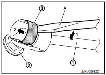
SPINDLE UNIT
SPINDLE UNIT : Removal and Installation
REMOVAL
- Support back door using a suitable tool.
WARNING: Bodily injury may occur if the back door is not supported properly when removing the back door spindle unit.
- Partially remove headlining (rear edge). Refer to INT-29, "Exploded View".
- Remove ball socket spring (B) from spindle unit (1) using a suitable tool (A).
- Disconnect the harness connector from the spindle unit and remove.
INSTALLATION
Installation is in the reverse order of removal.
CAUTION:
- When reusing stud ball, always apply locking sealant before installing stud ball to back door.
- After installation, check back door open/close, lock/unlock operation.
- Perform calibration of automatic back door position information. Refer to DLK-103, "Work Procedure".
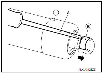
BACK DOOR STAY
BACK DOOR STAY : Removal and Installation
REMOVAL
- Support the back door using a suitable tool.
WARNING: Body injury may occur if no supporting rod is holding the back door open when removing the back door stay.
- Releaase the metal clip (3) located on the connection between the back door stay (1) and the stud ball (2) (back door side) using a suitable tool (A).
- Remove the back door stay (back door side).
- Repeat procedure for removing back door stay from body side.
INSTALLATION
Installation is in the reverse order of removal.
CAUTION: After installation, check the back door open/close operation.
TOUCH SENSOR
TOUCH SENSOR : Removal and Installation
CAUTION:
Use care not to bend touch sensor.
REMOVAL
- Release the spindle unit from the stud ball (with power back door).
- Release the back door stay from the stud ball (without power back door).
- Release touch sensor clips using a suitable tool.
- Disconnect the harness connector from the touch sensor and remove.
INSTALLATION
Installation is in the reverse order of removal.
CAUTION: After installation, check back door open/close and lock/unlock operation.
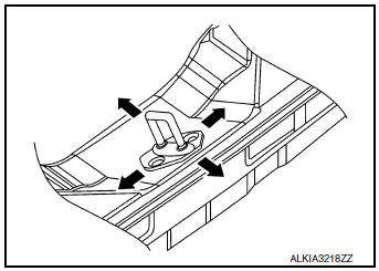
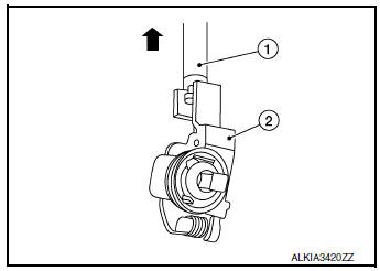
EMERGENCY LEVER
EMERGENCY LEVER : Unlock procedures
UNLOCK PROCEDURES
NOTE: If back door lock cannot be unlocked due to a malfunction or battery discharge, perform the following procedures to unlock back door assembly.
- From inside the vehicle, rotate emergency lever (1) in the direction shown to unlock.
FUEL FILLER LID OPENER
Exploded View
- Fuel filler lid release cable
- Fuel filler lid release handle
- Spring
- Bumper rubber
- Fuel filler lid lock
- Screw
FUEL FILLER LID
FUEL FILLER LID : Removal and Installation
REMOVAL
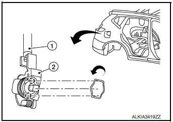
- Remove fuel cap pin (1).
- Remove screws(2) and fuel filler lid (1).
- Remove fuel filler lid spring (1) and bumper rubber (2) from fuel filler lid (if necessary).
INSTALLATION
Installation is in the reverse order of removal.
CAUTION: After installation, check fuel filler lid open/close, lock/unlock operation.
FUEL FILLER LID LOCK
FUEL FILLER LID LOCK : Removal and Installation
REMOVAL
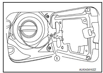
- Remove luggage side lower finisher (RH). Refer to INT-34, "LUGGAGE SIDE LOWER FINISHER : Removal and Installation - With Third Row Seat" (With Third Row Seat) or INT-35, "LUGGAGE SIDE LOWER FINISHER : Removal and Installation - Without Third Row Seat" (Without Third Row Seat).
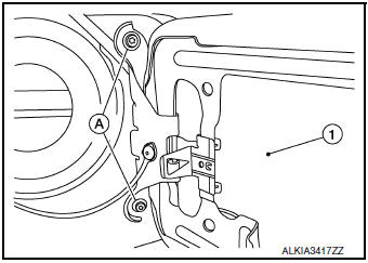
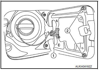
- Disconnect the fuel filler lid release cable (1) from the fuel filler lid lock (2).
- Rotate fuel filler lid lock to release pawls and remove.
 : Pawl
INSTALLATION
Installation is in the reverse order of removal.
CAUTION: After installation, check fuel filler lid open/close, lock/unlock operation.
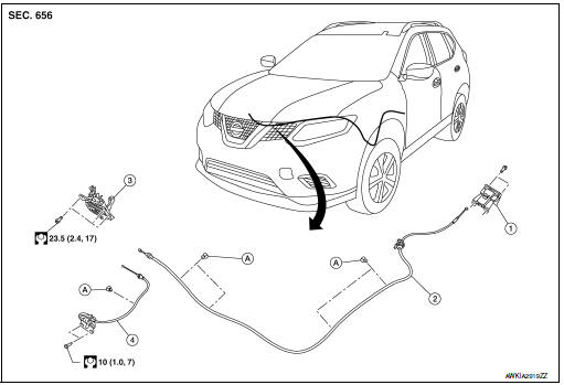
FUEL FILLER LID RELEASE CABLE
FUEL FILLER LID RELEASE CABLE : Removal and Installation
REMOVAL
- Partially remove front floor trim. Refer to INT-26, "Removal and Installation".
- Remove rear floor trim. Refer to INT-26, "Removal and Installation".
- Remove the fuel filler lid/hood lock release handle bolts (A)
- Disconnect the fuel filler lid release cable (2) from fuel filler lid release handle (1).
- Disconnect the fuel filler lid release cable (1) from fuel filler lid lock (2).
- Release the clips and remove fuel filler lid release cable.
INSTALLATION
Installation is in the reverse order of removal.
CAUTION: After installation, check fuel filler lid open/close, lock/unlock operation.
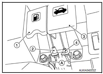
FUEL FILLER LID RELEASE HANDLE
FUEL FILLER LID RELEASE HANDLE : Removal and Installation
REMOVAL
- Remove fuel filler lid/hood lock release handle bolts (A).
- Disconnect fuel filler lid release cable (2) from fuel filler lid release handle (1).
- Disconnect hood lock release cable (4) from hood lock release handle (3).
- Remove fuel filler lid release handle.
INSTALLATION
Installation is in the reverse order of removal.
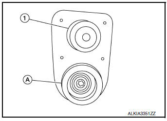
DOOR SWITCH
Removal and Installation
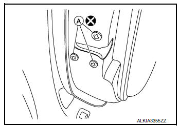
REMOVAL
- Remove the door switch bolt (A).
- Disconnect the harness connector from the door switch (1) and remove.
INSTALLATION
Installation is in the reverse order of removal.
DOOR REQUEST SWITCH
DRIVER SIDE
DRIVER SIDE : Removal and Installation
The driver side door request switch and driver side outside handle are serviced as an assembly. Refer to DLK- 257, "OUTSIDE HANDLE : Removal and Installation".
PASSENGER SIDE
PASSENGER SIDE : Removal and Installation
The passenger side door request switch and passenger side outside handle are serviced as an assembly.
Refer to DLK-257, "OUTSIDE HANDLE : Removal and Installation".
BACK DOOR
BACK DOOR : Removal and Installation
REMOVAL
- Remove back door finisher. Refer to INT-38, "Removal and Installation".
- Disconnect the harness connector from the back door request switch.
- Release pawls and remove back door request switch.
INSTALLATION
Installation is in the reverse order of removal.
INSIDE KEY ANTENNA
INSTRUMENT CENTER
INSTRUMENT CENTER : Removal and Installation
REMOVAL
- Remove front air control or A/C switch assembly. Refer to HAC-181, "Removal and Installation" (MANUAL AIR CONDITIONING) or HAC-102, "Removal and Installation" (AUTOMATIC AIR CONDITONING).
- Disconnect the harness connector from the inside key antenna (instrument center).
- Release pawls and remove inside key antenna (instrument center).
INSTALLATION
Installation is in the reverse order of removal.
CONSOLE
CONSOLE : Removal and Installation
REMOVAL
- Remove rear floor trim. Refer to INT-26, "Removal and Installation".
- Disconnect the harness connector (A) from the inside key antenna (console) (1).
- Release pawls and remove inside key antenna (console).
 : Pawl
INSTALLATION
Installation is in the reverse order of removal.
OUTSIDE KEY ANTENNA
DRIVER SIDE
DRIVER SIDE : Removal and Installation
The driver side outside key antenna and driver side outside handle are serviced as an assembly. Refer to DLK-257, "OUTSIDE HANDLE : Removal and Installation".
PASSENGER SIDE
PASSENGER SIDE : Removal and Installation
The passenger side outside key antenna and passenger side outside handle are serviced as an assembly.
Refer to DLK-257, "OUTSIDE HANDLE : Removal and Installation".
REAR BUMPER
REAR BUMPER : Removal and Installation
REMOVAL
- Remove rear bumper fascia. Refer to EXT-20, "Removal and Installation".
- Disconnect the harness connector (B) from the outside key antenna (rear bumper).
- Release clips (A) and remove outside key antenna (1)
INSTALLATION
Installation is in the reverse order of removal.
INTELLIGENT KEY WARNING BUZZER
Removal and Installation
REMOVAL
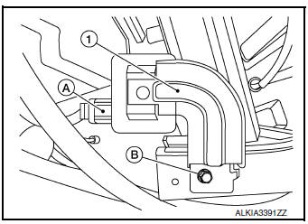
- Remove front combination lamp (RH). Refer to EXL-119, "Removal and Installation" (HALOGEN HEADLAMP) or EXL-268, "Removal and Installation" (LED HEADLAMP).
- Disconnect the harness connector (A) from the Intelligent Key warning buzzer (1).
- Remove bolt (B) and Intelligent Key warning buzzer.
INSTALLATION
Installation is in the reverse order of removal.
BACK DOOR WARNING CHIME
Removal and Installation
REMOVAL
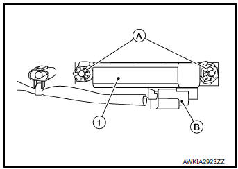
- Remove the rear bumper fascia. Refer to EXT-20, "Removal and Installation".
- Disconnect the harness connector from the back door warning chime.
- Remove nuts (A) and back door warning chime (1).
INSTALLATION
Installation is in the reverse order of removal.
INTELLIGENT KEY BATTERY
Removal and Installation
- Release the lock knob on the back of the Intelligent Key and remove the key.
- Insert a suitable tool (A) wrapped with a cloth into the slit of the corner and twist it to separate the upper part from the lower part.
CAUTION:
- Do not insert a tool into the notches of the Intelligent Key to pry it open, as this may damage the circuit board.
- Do not use excessive force when opening the intelligent key, as this may result in damage to the internal components.
- Do not touch the circuit board or battery terminal.
- The key fob is water-resistant. However, if it does get wet, immediately wipe it dry.
- Replace the battery with a new one.
Battery replacement :Coin-type lithium battery (CR2025)
- Align the tips of the upper and lower parts, and then push them together until unit is securely closed.
CAUTION:
- When replacing battery, keep dirt, grease, and other foreign materials off the electrode contact area.
- After replacing the battery, check that all Intelligent Key functions work normally.
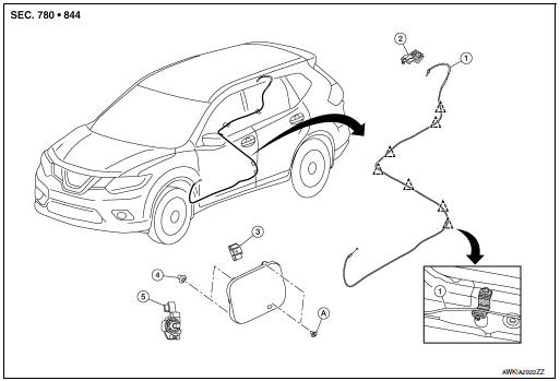
AUTOMATIC BACK DOOR CONTROL MODULE
Removal and Installation
REMOVAL
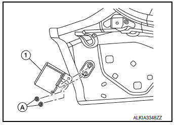
- Remove the luggage side lower finisher (LH). Refer to INT-34, "LUGGAGE SIDE LOWER FINISHER : Removal and Installation - With Third Row Seat".
- Disconnect the harness connectors from the automatic back door control module.
- Remove nuts (A) and automatic back door control module (1).
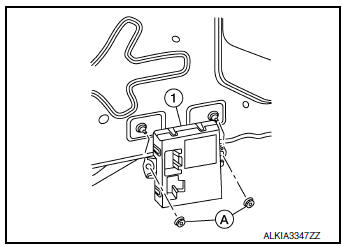
INSTALLATION
Installation is in the reverse order of removal.
AUTOMATIC BACK DOOR MAIN SWITCH
Removal and Installation
REMOVAL
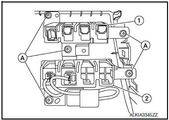
- Remove the instrument lower panel LH. Refer to IP-22, "Removal and Installation".
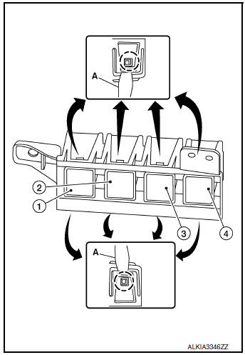
- Remove the screws (A) that retain the upper (1) and lower (2) switch carriers.
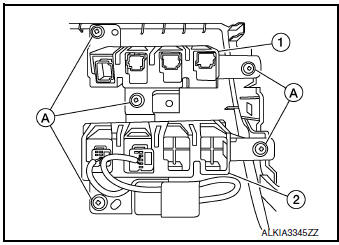
- Release pawls using a suitable tool (A), then remove the automatic
back door main switch (4) from the upper switch carrier.
(1): Traction control switch
(2): Sport mode switch
(3): Automatic back door switch
(4): Automatic back door main switch
INSTALLATION
Installation is in the reverse order of removal.
AUTOMATIC BACK DOOR SWITCH
Removal and Installation
REMOVAL
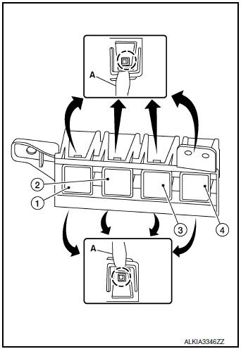
- Remove the instrument lower panel LH. Refer to IP-22, "Removal and Installation".
- Remove the screws (A) that retain the upper (1) and lower (2) switch carriers.
- Release pawls using a suitable tool (A), then remove the automatic
back door switch (3) from the upper switch carrier.
(1): Traction control switch
(2): Sport mode switch
(3): Automatic back door switch
(4): Automatic back door main switch
INSTALLATION
Installation is in the reverse order of removal.
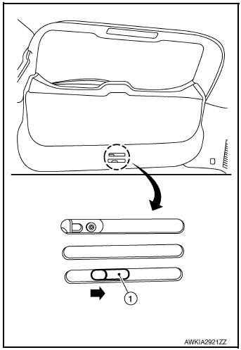
AUTOMATIC BACK DOOR CLOSE SWITCH
Removal and Installation
REMOVAL
- Release the automatic back door close switch (1) pawls using a
suitable tool.
 : Pawl
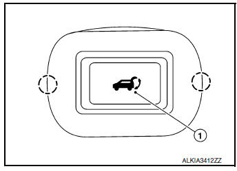
- Disconnect the harness connector (A) from the automatic back door close switch (1) and remove.
- Release pawls and remove automatic back door request switch
finisher (1) (if necessary)
 : Pawl
INSTALLATION
Installation is in the reverse order of removal.
 Symptom diagnosis
INTELLIGENT KEY SYSTEM SYMPTOMS
Symptom Table
CAUTION:
Perform the self-diagnosis with CONSULT before the symptom diagnosis. Perform
the trouble diagnosis
if any DTC is detected.
Sym ...

Other materials:
Water hose
Exploded View
Water outlet
Hose clamp
Water hose A
Clip
CVT oil warmer
Transaxle assembly
Water hose B
Heater thermostat
Water hose C
: Always replace after every
disassembly.
: N·m (kg-m, ft-lb)
Removal and Installation
REMOVAL
WARNING:
Do not remove the rad ...
Basic inspection
DIAGNOSIS AND REPAIR WORK FLO
Work Flow
OVERALL SEQUENCE
DETAILED FLOW
1.GET INFORMATION FOR SYMPTOM
Get detailed information from the customer about the symptom (the
condition and the environment when
the incident/malfunction occurs).
Check operation condition of the ...
Symptom diagnosis
DRIVER ASSISTANCE SYSTEM SYMPTOMS
Symptom Table
LANE DEPARTURE WARNING SYSTEM SYMPTOMS
NOTE:
Refer to the following the operation condition of the Lane Departure Warning
system.
Lane Departure Warning system: DAS-16, "LDW : System
Description".
BLIND SPOT WARNING ...
