Nissan Rogue Service Manual: Water hose
Exploded View
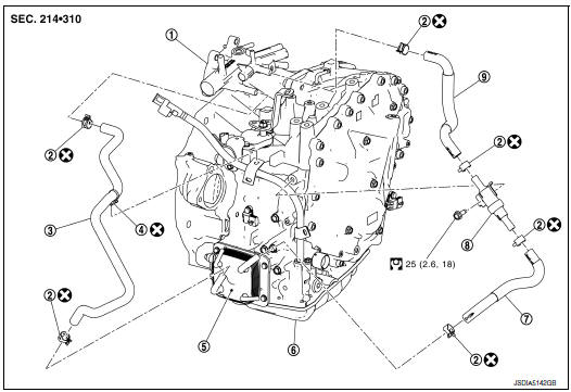
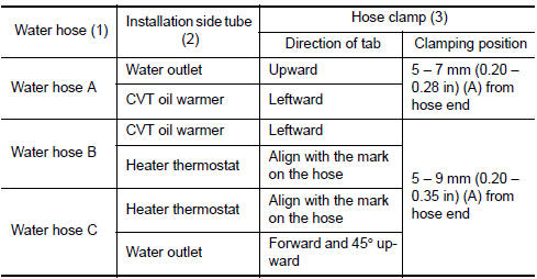
- Water outlet
- Hose clamp
- Water hose A
- Clip
- CVT oil warmer
- Transaxle assembly
- Water hose B
- Heater thermostat
- Water hose C
 : Always replace after every
disassembly.
: Always replace after every
disassembly.
 : N·m (kg-m, ft-lb)
Removal and Installation
REMOVAL
WARNING: Do not remove the radiator cap when the engine is hot. Serious burns could occur from high pressure engine coolant escaping from the radiator. Wrap a thick cloth around the cap. Slowly turn it a quarter turn to allow built-up pressure to escape. Carefully remove the cap by turning it all the way.
CAUTION: Perform when the engine is cold.
NOTE: When removing components such as hoses, tubes/lines, etc., cap or plug openings to prevent fluid from spilling.
- Remove battery tray. Refer to PG-76, "Removal and Installation (Battery Tray)".
- Remove engine under cover. Refer to EXT-16, "Exploded View".
- Remove CVT fluid charging pipe. Refer to TM-220, "Exploded View".
- Remove fender protector side cover. Refer to EXT-28, "FENDER PROTECTOR : Exploded View".
- Remove water hose A, B, C, and heater thermostat.
INSTALLATION
Installation is in the reverse order of removal.
CAUTION:
- Do not reuse hose clamps.
- Do not reuse hose clip
- Securely install the water hose clip to the bracket hole of charging pipe.
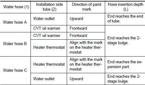
- Refer to the following when installing water hoses.
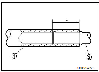
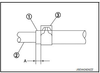
- Refer to the followings when installing hose clamp.
CAUTION: Hose clamp should not interfere with the bulge of tube.
Inspection
INSPECTION AFTER REMOVAL
Heater Thermostat
- Fully immerse the heater thermostat 1 in a container (A) filled with water. Continue heating the water while stirring.
- Continue heating the heater thermostat for 5 minutes or more after bringing the water to a boil.
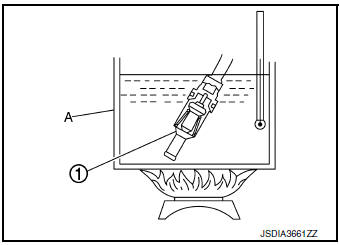
- Quickly take the heater thermostat out of the hot water, measure the heater thermostat within 10 seconds.
- Place dial indicator (A) on the pellet B and measure the elongation from the initial state.
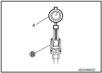
Standard : Refer to TM-226, "Heater Thermostat".
- If out of standard, replace heater thermostat.
INSPECTION AFTER INSTALLATION
Start the engine, and check the joints for coolant leakage.
 Differential side oil seal
Exploded View
Transaxle assembly
Differential side oil seal (left side)
Differential side oil seal (right side)
(FWD models only)
: Always replace after every
disassembly.
: Appl ...
 Fluid cooler hose
Exploded View
COMPONENT PARTS LOCATION
Transaxle assembly
Fluid cooler hose A
Hose clamp
Fluid cooler hose B
CVT oil warmer
To radiator
: Always replace after every
disassem ...
Other materials:
Wiring diagram
NVIS
Wiring Diagram
VEHICLE SECURITY SYSTEM
Wiring Diagram
...
The fuel gauge does not move
Description
Fuel gauge does not move from a certain position.
Diagnosis Procedure
1.CONDUCTING THE COMBINATION METER SELF-DIAGNOSIS MODE
Perform the self-diagnosis mode of combination meter, and then check that the
fuel gauge operates normally.
Refer to MWI-19, "Description".
I ...
Tire pressure sensor
Exploded View
Tire pressure sensor
O-ring
Valve stem nut
Valve core
Valve cap
Valve stem assembly
: Parts that are replaced as a
set when the tire is replaced.
Removal and Installation
REMOVAL
Remove wheel and tire using power tool.
Remove v ...
