Nissan Rogue Service Manual: Differential side oil seal
Exploded View
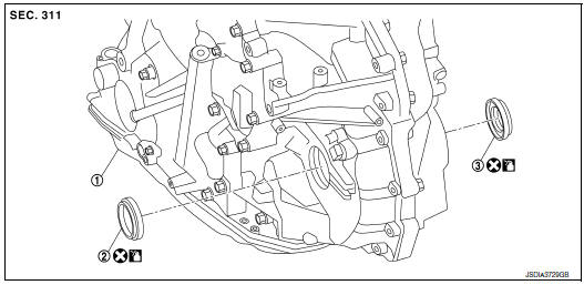
- Transaxle assembly
- Differential side oil seal (left side)
- Differential side oil seal (right side) (FWD models only)
 : Always replace after every
disassembly.
: Always replace after every
disassembly.
 : Apply CVT fluid
Removal and Installation
REMOVAL
NOTE: When removing components such as hoses, tubes/lines, etc., cap or plug openings to prevent fluid from spilling.
- Remove front drive shaft. Refer to FAX-18, "Removal and Installation (LH)" (FWD) or FAX-50, "Removal and Installation (LH)" [LH (AWD)]or FAX-52, "Removal and Installation (RH)" [RH(AWD)].
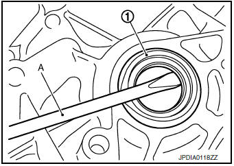
- Remove differential side oil seal (1) using suitable tool (A).
CAUTION: Be careful not to scratch transaxle case and converter housing.
INSTALLATION
Installation is in the reverse order of removal.
CAUTION:
- Do not reuse differential side oil seal.
- Apply CVT fluid to differential side oil seals.
- When inserting the drive shaft, be sure to use Tool.
Tool number: KV38107900
Install each differential side oil seal evenly using suitable tool so that differential side oil seal protrudes by the dimension (C) and (D) respectfully.
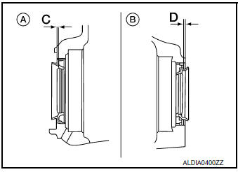
(A) : Differential side oil seal (LH)
(B) : Differential side oil seal (RH) (FWD models only)
Dimension (C) :Height difference from case end surface is within 1.8 ± 0.5 mm (0.071 ± 0.020 in).
Dimension (D) :Height difference from case end surface is within 2.2 ± 0.5 mm (0.087 ± 0.020 in).
NOTE: The reference is the installation direction of the differential side oil seal.
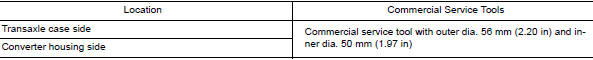
Drift to be used:
Inspection and Adjustment
INSPECTION AFTER INSTALLATION
Check for CVT fluid leakage. Refer to TM-190, "Inspection".
ADJUSTMENT AFTER INSTALLATION
Adjust the CVT fluid level. Refer to TM-192, "Adjustment".
 Output speed sensor
Exploded View
Transaxle assembly
Output speed sensor
O-ring
Always replace after every
disassembly.
: N·m (kg-m, in-lb)
: Apply CVT fluid
Removal and Installation
REMOVAL
...
 Water hose
Exploded View
Water outlet
Hose clamp
Water hose A
Clip
CVT oil warmer
Transaxle assembly
Water hose B
Heater thermostat
Water hose C
: Always replace after every
di ...
Other materials:
Symptom diagnosis
SQUEAK AND RATTLE TROUBLE DIAGNOSES
Work Flow
CUSTOMER INTERVIEW
Interview the customer if possible, to determine the conditions that exist
when the noise occurs. Use the Diagnostic
Worksheet during the interview to document the facts and conditions when the
noise occurs and any
custome ...
Changing engine oil filter
>
Changing engine oil filter
Park the vehicle on a level surface and apply
the parking brake.
Turn the engine off.
Place a large drain pan under the oil filter B .
Remove pins C from the right engine protector
located inside right wheel well, remove
protector. Remove oil ...
System description
COMPONENT PARTS
Component Part Location
RH side of engine compartment
RH front of vehicle (view with front
bumper fascia removed)
No.
Component
Description
1
IPDM E/R
Refer to PCS-5, "RELAY CONTROL SYSTEM : System Description".
...
