Nissan Rogue Service Manual: System description
COMPONENT PARTS
Component Part Location
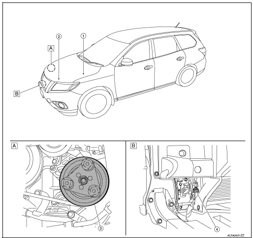
- RH side of engine compartment
- RH front of vehicle (view with front bumper fascia removed)
|
No. |
Component |
Description |
| 1 | IPDM E/R | Refer to PCS-5, "RELAY CONTROL SYSTEM : System Description". |
| 2 | ECM | The ECM sends a compressor ON request to the IPDM E/R based on the status of engine operation and load as well as refrigerant pressure information. If all the conditions are met for A/C operation, the ECM transmits the compressor ON request to the IPDM E/R. |
| 3 | A/C Compressor | Vaporized refrigerant is drawn into the A/C compressor from the evaporator, where it is compressed to a high pressure, high temperature vapor. The hot, compressed vapor is then discharged to the condenser. |
| 4 | Refrigerant pressure sensor | Refer to EC-28, "Refrigerant Pressure Sensor". |
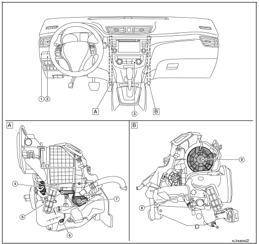
- Left side of A/C unit
- Right side of A/C unit
|
No. |
Component |
Description |
| 1 | Front blower relay | The front blower relay controls the flow of current to
fuse 17 and 27 in the Fuse Block (J/B). The relay is grounded when the ignition switch is in the ON position. |
| 2 | BCM | The BCM receives the fan ON and A/C ON signals from the front air control and sends a compressor ON request to the ECM. |
| 3 | Front air control | The front air control controls the operation of the A/C and heating system based on inputs from the temperature control knob, the mode switches, the blower control dial, the intake sensor, and inputs received from the ECM across the CAN. Diagnosis of the front air control can be performed using the CONSULT. There is no self-diagnostic feature available. |
| 4 | Variable blower control | The variable blower control controls the speed of the blower motor by controlling the ground circuit of the blower motor. The front air control provides voltage to the gate of the variable blower control based on the position of the blower control dial. |
| 5 | Intake door motor | The intake door motor controls the position of the intake door. Fresh air is allowed to enter the cabin in one position, and recirculated inside air is allowed to enter in the other position. The intake door motor receives position commands from the front air control. |
| 6 | Intake sensor | The intake sensor measures the temperature of the front evaporator fins. The sensor uses a thermistor which is sensitive to the change in temperature. The electrical resistance of the thermistor decreases as temperature increases. |
| 7 | Air mix door motor | The air mix door controls the mix of hot or cold air that enters the ventilation system. It is controlled by the front air control based on the position of the temperature dial. The air mix door motor LH receives position commands from the front air control. |
| 8 | Mode door motor | The mode door controls the direction the conditioned air passes
through the ventilation system. Through a series of levers and gears, the mode door controls the defrost door, the foot door, and the vent door. There are 5 preset positions: VENT, B/L, FOOT, D/F, and DEF. The mode door motor receives position commands from the front air control. |
| 9 | Front blower motor | The blower motor varies the speed at which the air flows through the ventilation system. |
SYSTEM
System Description
SYSTEM DIAGRAM
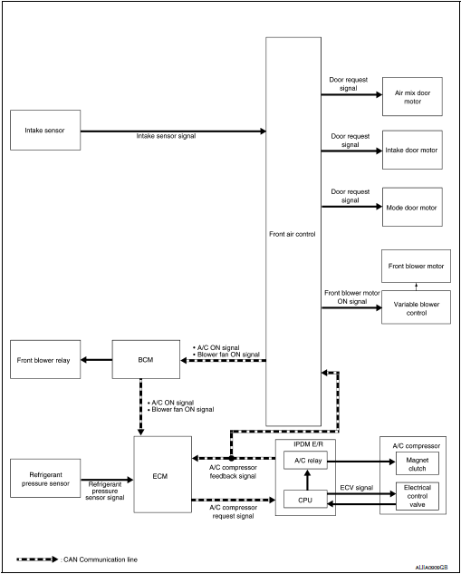
SYSTEM DESCRIPTION
- The manual air conditioning system is controlled by a sequence of functions from the front air control, BCM, ECM, and IPDM E/R.
Controlled by front air control:
- HAC-119, "Air Flow Control"
- HAC-119, "Air Inlet Control"
- HAC-119, "Air Outlet Control"
- HAC-119, "Compressor Control"
- HAC-120, "Door Control"
- HAC-123, "Temperature Control"
Controlled by BCM:
- Air conditioning request signal.
Refer to BCS-8, "BODY CONTROL SYSTEM : System Description" (with Intelligent Key system) or BCS-80, "BODY CONTROL SYSTEM : System Description" (without Intelligent Key system).
Control by ECM
- Cooling fan control Refer to EC-46, "COOLING FAN CONTROL : System Description".
- Air conditioning cut control Refer to EC-45, "AIR CONDITIONING CUT CONTROL : System Description".
Control by IPDM E/R
- Relay control Refer to PCS-5, "RELAY CONTROL SYSTEM : System Description".
- Cooling fan control Refer to EC-46, "COOLING FAN CONTROL : System Description".
Air Flow Control
DESCRIPTION
- Front air control changes duty ratio of front blower motor control signal to control air flow continuously. When air flow is increased, duty ratio of front blower motor control signal gradually increases to prevent a sudden increase in air flow.
- In addition to manual control, air flow control is composed of fan speed control at door motor operation.
FAN SPEED CONTROL AT DOOR MOTOR OPERATION
When mode door motor is activated while air flow is more than the specified value, front air control temporarily reduces fan speed so that mode door moves smoothly.
Air Inlet Control
The intake door position is automatically controlled in MAX A/C and DEF modes. The intake door is controlled by customer input in the other modes.
Air Outlet Control
Air outlet control is controlled by customer input. When the A/C is turned off by turning the blower control dial fully counterclockwise, the front air control retains the current selections and returns to these selections the next time the blower control dial is turned to any fan position.
NOTE: If ambient temperature is excessively low, D/F is selected to prevent windshield fogging when air outlet is set to FOOT.
Compressor Control
DESCRIPTION
In order for the IPDM E/R to complete a compressor ON request, the following conditions must be met:
- The BCM detects a Fan ON signal from the front air control. The front air control grounds the fan ON signal monitored by the BCM when the blower speed dial is in any of the fan speed positions.
- The BCM detects an A/C ON signal from the front air control. The front air control grounds the A/C ON signal monitored by the BCM when:
- The A/C switch is pressed. The A/C switch LED illuminates and the front air control grounds the A/C ON signal monitored by the BCM. Any mode control button except D/F may be selected.
- The A/C switch is OFF, and the MAX A/C button is pressed. The A/C switch LED will automatically illuminate and the front air control grounds the A/C ON signal monitored by the BCM.
- The A/C switch is OFF, and the mode button for either D/F or DEF is selected. The front air control grounds the A/C ON signal monitored by the BCM, but it does not illuminate the A/C switch LED
NOTE: If the compressor was engaged by pressing the D/F or DEF mode buttons, and the time spent in either mode exceeds 1 minute, then the compressor stays requested, even when modes other than D/F or DEF are selected, until either:
- The ignition switch is turned OFF.
- The blower speed dial is turned completely counterclockwise to the OFF position.
- The A/C switch is manually turned OFF.
In other words, the compressor ON request cannot be turned off in D/F or DEF modes
REFRIGERANT PRESSURE PROTECTION
The refrigerant system is protected against excessively high- or low-pressures by the refrigerant pressure sensor, located on the liquid tank on the condenser. The refrigerant pressure sensor detects the pressure inside the refrigerant line and sends a voltage signal to the ECM. If the system pressure rises above or falls below the following values, the ECM requests the IPDM E/R to de-energize the A/C relay and disengage the compressor.
- 3.12 MPa (31.82 kg/cm2, 452.4 psi) or more (When the engine speed is less than 1,500 rpm)
- 2.74 MPa (27.95 kg/cm2, 397.3 psi) or more (When the engine speed is 1,500 rpm or more)
- 0.14 MPa (1.43 kg/cm2, 20.3 psi) or less
PRESSURE RELIEF VALVE
The refrigerant system is also protected by a pressure relief valve, located in the rear head of the compressor.
When the pressure of refrigerant in the system increases to an abnormal level [more than 2,990 kPa (30.5 kg/ cm2, 433.6 psi)], the release port on the pressure relief valve automatically opens and releases refrigerant into the atmosphere.
COMPRESSOR OIL CIRCULATION CONTROL
When the engine starts while the engine coolant temperature is 56°C (133°F) or less, ECM activates the compressor for approximately 6 seconds and circulates the compressor lubricant once.
LOW TEMPERATURE PROTECTION CONTROL
- When the intake sensor detects that the front evaporator fin temperature is 1.5°C (35°F) or less, the front air control requests the BCM to turn the compressor OFF, and stops the compressor.
- When the front evaporator fin temperature returns to 5.0°C (41°F) or more, the compressor is activated.
OPERATING RATE CONTROL
When the set temperature is other than fully cold or the air outlet is “VENT”, “B/L” or “FOOT”, the front air control controls the compressor activation depending on ambient temperature.
Door Control
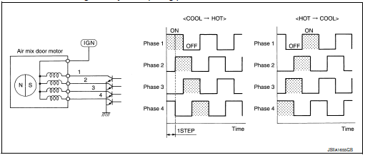
AIR MIX DOOR MOTOR
- DESCRIPTION The step motor system is adopted for air mix door motor.
- When a drive signal is input from front air control to door motor, a step motor built into the door motor rotates according to the drive signal, and then stops at the target door position.
- Rotation of motor is transmitted to air mix door (upper air mix door and lower air mix door) by link, rod and lever, then air flow temperature is switched.
DRIVE METHOD
- The 4 drive coils are excited in sequence in order to drive the motor.
- Direction of rotation is changeable by recomposing pattern of excitation.
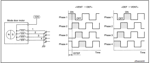
MODE DOOR MOTOR
DESCRIPTION
- The step motor system is adopted for mode door motor.
- When a drive signal is input from front air control to door motor, a step motor built into the door motor rotates according to the drive signal, and then stops at the target door position.
- Rotation of motor is transmitted to mode door (center ventilator and defroster door, sub defroster door, side ventilator door, and foot door) by link, rod, and lever, then air outlet is switched.
DRIVE METHOD
- The 4 drive coils are excited in sequence in order to drive the motor.
- Direction of rotation is changeable by recomposing pattern of excitation.
INTAKE DOOR MOTOR
- Motor operates intake door according to control signal from front air control.
- Rotation of motor is transmitted to intake door by lever, then air inlet is switched.
SWITCHES AND THEIR CONTROL FUNCTION
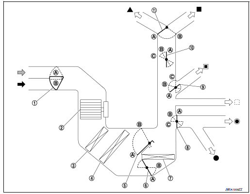
- Intake door
- Blower motor
- Air conditioner filter
- Evaporator
- Upper air mix door (driver side/passenger side)
- Lower air mix door (driver side/passenger side)
- Heater core
- Foot door
- Side ventilator door
- Sub defroster door
- Center ventilator and defroster door
 Fresh air intake
 Recirculation air
 Discharge air
 Defroster
 Center ventilator
 Side ventilator
 Rear ventilator
 Front foot
 Rear foot
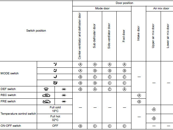
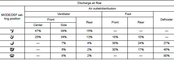
AIR DISTRIBUTION
Temperature Control
- When the ignition switch is in the ON position, the customer uses the front air control temperature control dial to set the desired temperature.
- The front air control calculates the target front air mix door opening angle depending on the selected temperature, intake temperature sensor, engine coolant temperature and rpm, and ambient temperature.
- Front air mix door is controlled depending on the comparison of current front air mix door opening angle and target front air mix door opening angle.
- Regardless of ambient temperature, the front air mix door is fixed at the fully cold position when the temperature control dial is set at the full cold position and fixed at the fully hot position when the temperature control dial is set at the full hot position.
OPERATION
Switch Name and Function
A/C Switch Assembly
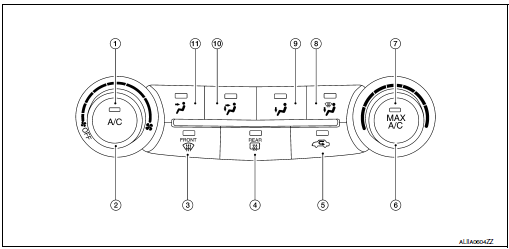
- A/C switch
- Blower control dial (with OFF switch)
- DEF switch
- Rear DEF switch
- REC switch
- Temperature control dial
- MAX A/C switch
- D/F switch
- FOOT switch
- B/L switch
- VENT switch
Switch Operation
| A/C switch | Switches the compressor control switch indicator between ON ⇔ OFF
with each press while front
blower fan is activated. The circuit used by the BCM to detect an A/C ON
request is grounded. NOTE: When front blower fan is OFF, the compressor control cannot be activated. |
| Blower control dial (with OFF switch) |
NOTE: When blower control dial is turned to any ON position the air conditioning system is activated. (Compressor control state returns to the previous state before air conditioning system was turned OFF.) |
| DEF switch | Switches DEF mode (switch indicator) between ON ⇔ OFF with each
press.
NOTE: When front blower fan is OFF, DEF cannot be activated. |
| MAX A/C switch | Switches the MAX A/C and compressor control switch indicators
between ON ⇔ OFF with each press
while front blower fan is activated.
NOTE: When front blower fan is OFF, the compressor control cannot be activated. |
| MODE switches | Selects air outlet from VENT, B/L, FOOT, and D/F. NOTE: When the air conditioning system is OFF, the air outlet can still be selected. |
| REC switch |
NOTE:
|
| Temperature control dial |
|
DIAGNOSIS SYSTEM (HVAC)
Description
Air conditioning system performs self-diagnosis, operation check, function diagnosis, and various settings using diagnosis function of each control unit.
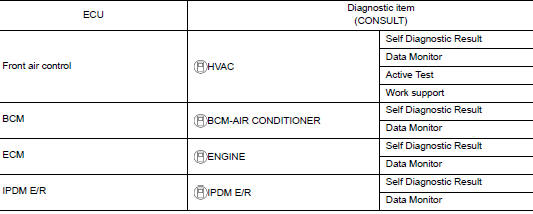
CONSULT Function (HVAC)
CONSULT can display each diagnosis item using the diagnosis test modes as shown.
CONSULT application items
|
Diagnosis mode |
Description |
| Self-Diagnostic Result | Displays the diagnosis results judged by A/C auto amp. |
| Data Monitor | Displays A/C auto amp. input/output data in real time. |
| Work support | Changes the setting for each system function. |
| Active Test | The signals used to activate each device are forcibly supplied from front air control. |
| ECU Identification | Displays the A/C auto amp. number. |
SELF-DIAGNOSTIC RESULT
Refer to HAC-134, "DTC Index".
Display Item List
|
DTC |
Items (CONSULT screen terms) |
Diagnostic item is detected when... |
Possible cause |
| U1000 | CAN COMM CIRCUIT | When A/C auto amp. is not transmitting or receiving CAN communication signal for 2 or more seconds. | CAN communication system |
| U1010 | CONTROL UNIT (CAN) | When detecting error during the initial diagnosis of CAN controller of front air control. | Front air control |
| B24A4 | INTAKE TEMP SEN | Short or open circuit of the intake temperature sensor signal. |
|
| B24BB | AIRMIX ACTR | Short or open circuit of air mix door motor drive signal. |
|
| B24B7 | INTAKE ACTR | Short or open circuit of intake door motor drive signal. |
|
| B27B9 | MODE DOOR ACTR | Short or open circuit of mode door motor drive signal. |
|
DATA MONITOR
Display item list
|
Monitor item [Unit] |
Description |
|
| AMB TEMP SEN | [°C] | Ambient sensor value converted from ambient sensor signal received from ambient sensor |
| INT TEMP SEN | [°C] | Intake sensor value converted from intake sensor signal received from intake sensor |
| AMB SEN CAL | [°] | Ambient sensor value calculated by A/C auto amp. |
| INT TEMP CAL | [°C] | Intake sensor value calculated by A/C auto amp. |
| COMP REQ SIG | [On/Off] | Displays A/C switch ON/OFF status transmitted to other units via CAN communication |
| FAN REQ SIG | [On/Off] | Displays blower switch ON/OFF status transmitted to other units via CAN communication |
| FAN DUTY | [%] | Duty ratio of blower motor judged by A/C auto amp. |
| VEHICLE SPEED | [km/h (mph)] | Vehicle speed signal value received from meter via CAN communication |
WORK SUPPORT
|
Work item |
Description |
Reference |
| Door Motor Starting Position Reset | Starting position reset of air mix door motor and mode door motor can be performed. | HAC-151, "Work Procedure" |
| TARGET EVAPORATOR TEMP UPPER LIMIT SETTING | Set the target evaporator upper temperature limit. | HAC-150, "Target Evaporator Temp Upper Limit" |
NOTE: When the battery cable is disconnected from the negative terminal or when the battery voltage becomes 10V or less, the setting of WORK SUPPORT may be cancelled.
ACTIVE TEST
|
Test item |
Description |
| HVAC TEST | The operation check of A/C system can be performed by selecting the mode. Refer to the following table for the conditions of each mode. |
HVAC TEST
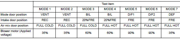
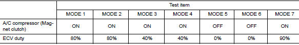
NOTE: Perform the inspection of each output device after starting the engine, because the A/C compressor has been operating.
DIAGNOSIS SYSTEM (IPDM E/R)
CONSULT Function (IPDM E/R)
APPLICATION ITEM
CONSULT performs the following functions via CAN communication with IPDM E/R.
|
Direct Diagnostic Mode |
Description |
| Ecu Identification | The IPDM E/R part number is displayed. |
| Self Diagnostic Result | The IPDM E/R self diagnostic results are displayed |
| Data Monitor | The IPDM E/R input/output data is displayed in real time. |
| Active Test | The IPDM E/R activates outputs to test components. |
| CAN Diag Support Mntr | The result of transmit/receive diagnosis of CAN communication is displayed. |
ECU IDENTIFICATION
The IPDM E/R part number is displayed.
SELF DIAGNOSTIC RESULT
Refer to PCS-20, "DTC Index".
DATA MONITOR
ACTIVE TEST
CAN DIAG SUPPORT MNTR
Refer to LAN-14, "CAN Diagnostic Support Monitor".
 Preparation
Special Service Tool
The actual shape of the tools may differ from those illustrated here.
Tool number
(TechMate No.)
Tool name
Description
—
(J-46534)
Trim Tool ...
 ECU diagnosis information
FRONT AIR CONTROL
Reference Value
TERMINAL LAYOUT
PHYSICAL VALUES
DTC Inspection Priority Chart
If some DTCs are displayed at the same time, perform inspections one by one
based ...
Other materials:
P0524 engine oil pressure
DTC Description
DTC DETECTION LOGIC
DTC No.
CONSULT screen terms
(Trouble diagnosis content)
DTC detecting condition
P0524
ENGINE OIL PRESSURE
(Engine oil pressure too low)
An EOP sensor signal voltage applied to ECM remains lower than the
specified
value c ...
Component parts
Component Parts Location
Instrument lower panel LH
No.
Component
Function
1
Combination meter
The combination meter transmittes the following signal via CAN
communications
to the TCM.
SPORT mode switch signal
...
Console box
Console box
Upper half
Pull up on the driver’s side latch to open the
upper half of the console box.
The upper half of the console box may be used for
storage of cellular phones. An access hole is
provided at the front of the upper half of the
console box for a phone or iPod® cord rout ...
