Nissan Rogue Service Manual: ECU diagnosis information
FRONT AIR CONTROL
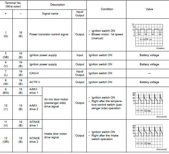
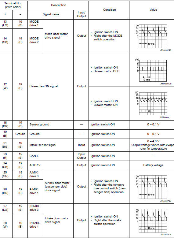
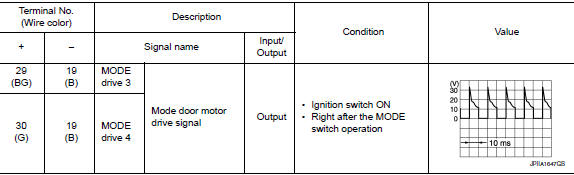
Reference Value
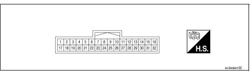
TERMINAL LAYOUT
PHYSICAL VALUES
DTC Inspection Priority Chart
If some DTCs are displayed at the same time, perform inspections one by one based on the following priority chart.
|
Priority |
Detected items (DTC) |
| 1 |
|
| 2 |
|
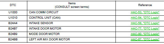
DTC Index
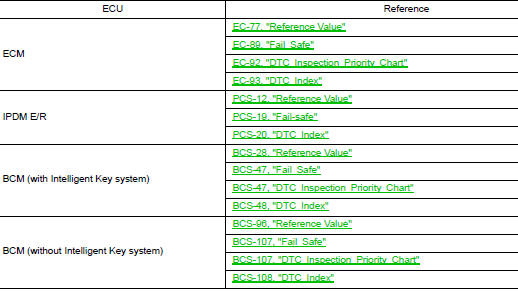
ECM, IPDM E/R, BCM
List of ECU Reference
 System description
COMPONENT PARTS
Component Part Location
RH side of engine compartment
RH front of vehicle (view with front
bumper fascia removed)
No.
Component
Description
...
 Wiring diagram
MANUAL AIR CONDITIONING SYSTEM
Wiring Diagram
...
Other materials:
U0101 CAN comm circuit
Description
CAN (Controller Area Network) is a serial communication line for real time
application. It is an on-vehicle multiplex
communication line with high data communication speed and excellent error
detection ability. Many electronic
control units are equipped onto a vehicle, and each co ...
System description
VENTILATION SYSTEM
System Description
OUTLINE
Automatic A/C
The ventilation system is controlled by the A/C switch assembly. For details
of the automatic air conditioner
system, refer to HAC-10, "System Description".
Manual A/C
The ventilation system is controlled by the front air ...
Removal and installation
CHASSIS CONTROL MODULE
Exploded View
Steering member
Chassis control module
Front
Removal and Installation
CAUTION:
When replacing chassis control module, configuration of chassis control module
is required. Refer to
DAS-205, "Work Procedure".
REMOVAL
NOTE:
...
