Nissan Rogue Service Manual: Symptom diagnosis
DRIVER ASSISTANCE SYSTEM SYMPTOMS
Symptom Table
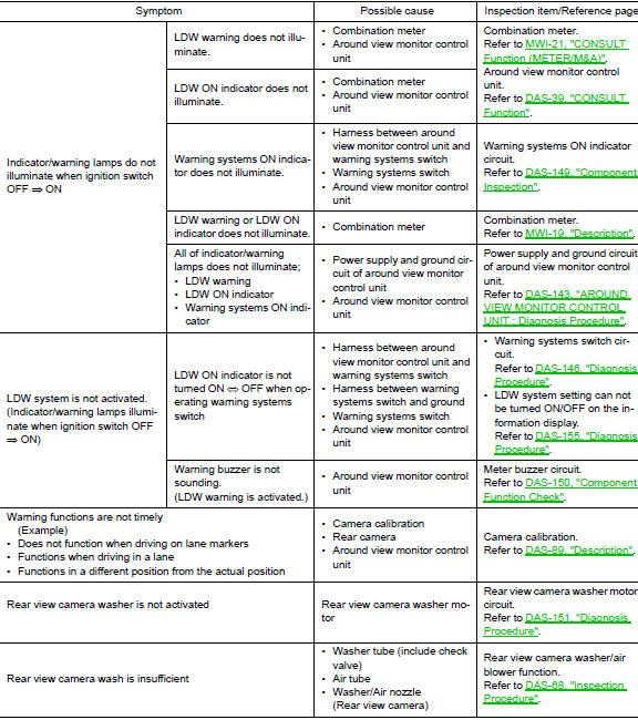
LANE DEPARTURE WARNING SYSTEM SYMPTOMS
NOTE: Refer to the following the operation condition of the Lane Departure Warning system.
- Lane Departure Warning system: DAS-16, "LDW : System Description".
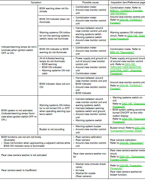
BLIND SPOT WARNING SYSTEM SYMPTOMS
NOTE: Refer to the following the operation condition of the Blind Spot Warning system.
- Blind Spot Warning system: DAS-20, "BSW : System Description".
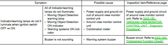
MOVING OBJECT DETECTION SYSTEM SYMPTOMS
NOTE: Refer to the following the operation condition of the Moving Object Detection system.
- Moving Object Detection system: DAS-26, "MOD : System Description".
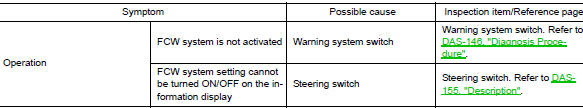
FORWARD COLLISION WARNING SYSTEM SYMPTOMS
NOTE: Refer to the following the operation condition of the Forward Collision Warning system.
- Forward Collision Warning system: DAS-29, "FCW : System Description".
SYSTEM SETTINGS CANNOT BE TURNED ON/OFF IN VEHICLE INFORMATION DISPLAY
Description
The system setting cannot be turned ON/OFF in the combination meter information display using the steering switch.
Diagnosis Procedure
1.CHECK DRIVER ASSISTNCE SYSTEM SETTING
- Ignition On.
- Check that the driver assistance system setting can be turned ON/OFF in the combination meter information display using the steering switch.
Is the inspection result normal? YES >> Inspection End.
NO >> GO TO 2.
2.CHECK STEERING SWITCH CIRCUIT
Check the steering switch. Refer to MWI-69, "Diagnosis Procedure".
Is the inspection result normal? YES >> GO TO 3.
NO >> Repair or replace harness or connector
3.CHECK STEERING SWITCH RESISTANCE
Check the steering switch resistance. Refer to MWI-69, "Component Inspection".
Is the inspection result normal? YES >> Replace combination meter. Refer to MWI-82, "Removal and Installation".
NO >> Replace steering switch. Refer to AV-211, "Removal and Installation".
SWITCH DOES NOT TURN ON / SWITCH DOES NOT TURN OFF
Description
The switch does not turn ON
- The driver assistance system does not turn On when the warning system switch is pressed.
The switch does not turn OFF
- The driver assistance system does not turn Off when the warning system switch is pressed.
Diagnosis Procedure
1.CHECK WARNING SYSTEM SWITCH CIRCUIT
Check the warning system switch circuit. Refer to DAS-146, "Diagnosis Procedure".
Is the inspection result normal? YES >> GO TO 2.
NO >> Repair or replace harness or connector.
2.CHECK WARNING SYSTEM SWITCH
Check the warning system switch. Refer to DAS-147, "Component Inspection".
Is the inspection result normal? YES >> Replace the around view monitor control unit. Refer to DAS-163, "Removal and Installation".
NO >> Replace the warning system switch. Refer to DAS-164, "Removal and Installation".
NORMAL OPERATING CONDITION
Description
PRECAUTIONS FOR FORWARD COLLISION WARNING (FCW)
- The forward collision warning system is designed to warn driver
before a collision but will not avoid a collision.
It is the driver's responsibility to stay alert, drive safely and be in control of the vehicle at all times.
- The radar sensor does not detect the following objects.
- Pedestrians, animals, or obstacles in the roadway.
- Oncoming vehicles
- Crossing vehicles
- The forward collision warning system does not function when a vehicle ahead is a narrow vehicle, such as a motorcycle.
- The radar sensor may not detect a vehicle ahead in the following conditions:
- Snow or heavy rain
- Dirt, ice, snow or other material covering the radar sensor
- Interference by other radar sources
- Snow or road spray from traveling vehicles is splashed
- Driving in a tunnel
- The radar sensor may not detect a vehicle when the vehicle ahead is being towed.
- When the distance to the vehicle ahead is too close, the beam of the radar sensor is obstructed.
- The radar sensor may not detect a vehicle when driving on a steep downhill slope or on roads with sharp curves.
- Excessive noise will interfere with the warning tone sound, and it may not be heard.
PRECAUTIONS FOR LANE DEPARTURE WARNING (LDW)
- The LDW system is only a warning device to inform the driver of a potential unintended lane departure. It will not steer the vehicle or prevent loss of control. It is the driver′s responsibility to stay alert, drive safely, keep the vehicle in the traveling lane, and be in control of the vehicle at all times.
- The rear view camera may not detect properly under the following conditions:
- When towing a trailer.
- When strong light enters the rear view camera. (For example, direct sunlight or headlight from the rear)
- When ambient brightness changes instantly. (For example, when the vehicle enters or exits a tunnel or passes under a bridge.)
- Automatic washer and blower may not be able to secure detection capability when excessive dirt adheres on the camera lens.
- LDW system may not function properly under the following conditions:
- Excessive noise (e.g. audio system volume, open vehicle window) will interfere with the chime sound, and it may not be heard.
- The rear view camera may not be able to detect properly under the following conditions:
- On roads where there are multiple parallel lane markers; lane markers that are faded or not painted clearly; yellow painted lane markers; non-standard lane markers; or lane markers covered with water, dirt, snow, etc.
- On roads where the discontinued lane markers are still detectable.
- On roads where there are sharply contrasting objects, such as shadows, snow, water, wheel ruts, seams or lines remaining after road repairs. (The LDW system could detect these items as lane markers.)
- On roads where the traveling lane merges or separates.
- When the vehicle′s traveling direction does not align with the lane marker.
- When the road surface is very dark due to scarce ambient light or impaired tail lamp.
- When driving on curved road, warning will be late on the outside of the curve due to the nature of the system.
PRECAUTIONS FOR BLIND SPOT WARNING (BSW)
- The BSW system is not a replacement for proper driving procedure and is not designed to prevent contact with vehicles or objects. When changing lanes, always use the side and rear mirrors and turn and look in the direction you will move to ensure it is safe to change lanes. Never rely solely on the BSW system.
- The rear camera may not detect properly under the following conditions:
- When towing a trailer.
- When strong light enters the rear camera. (For example, direct sunlight or headlight from the rear)
- When ambient brightness changes instantly. (For example, when the vehicle enters or exits a tunnel or passes under a bridge.)
- Automatic washer and blower may not be able to secure detection capability when excessive dirt adheres on the camera lens.
- The camera unit may not be able to detect when certain objects are present such as:
- Pedestrians, bicycles, animals
- Several types of vehicles such as motorcycles
- Oncoming vehicles
- A vehicle approaching rapidly from behind.
- A vehicle which your vehicle overtakes rapidly.
- The rear camera may not be able to detect properly when your vehicle travels beside the middle section of a vehicle with long wheelbase(e.g. trailer truck, semi-trailer, tractor).
- The rear camera detection zone is designed based on a standard lane width. When driving in a wider lane, the camera unit may not detect vehicles in an adjacent lane. When driving in a narrow lane, the camera unit may detect vehicles driving two lanes away.
- The rear camera is designed to ignore most stationary objects, however objects such as guardrails, walls, foliage and parked vehicles may occasionally be detected. This is a normal operating condition.
- The rear camera may detect reflection image of vehicles or roadside objects that are not actually in the detection zone, especially when the road is wet.
MOVING OBJECT DETECTION
- The Moving Object Detection system is not a replacement for proper driving procedure and is not designed to prevent contact with vehicles or objects. When backing up, always look in the direction the driver will move to ensure it is safe to proceed. Never rely solely on the Moving Object Detection system.
- Using the Moving Object Detection system under some road or weather condition could lead to improper system operation. Always rely on driver's own steering and braking operation to avoid accidents.
- The Moving Object Detection system may not provide a warning for vehicles that pass through the detection zone quickly.
- Do not use the Moving Object Detection system when towing a trailer.
- Excessive noise (e.g., audio system volume, open vehicle window) will interfere with the chime sound, and it may not be heard.
- A rear view camera may not detect approaching vehicles in certain situations:
- When a vehicle parked alongside obstructs the beam of the rear view camera.
- When the vehicle is parked in an angled parking space.
- When the vehicle is parked on an incline.
- When a vehicle turns into your vehicle’s aisle.
- When the angle formed by your vehicle and approaching vehicle is small.
- Severe weather or road spray conditions may reduce the ability of the radar to detect other vehicles.
- The rear view camera system may not detect:
- Small or moving object.
- Wedge-shaped objects.
- Object closer to the bumper than 30 cm (10 inch).
- Thin objects such as rope, wire, chain, etc.
- Do not use the MOD system under the following conditions because the system may not function properly:
- When driving with a tire that is not the within normal tire condition (example: tire wear, low pressure, spare tire, chain, non-standard wheels).
- When the vehicle is equipped with non-original brake parts or suspension parts.
 DTC/circuit diagnosis
U0121 VDC CAN 2
DTC Logic
DTC DETECTION LOGIC
NOTE:
If DTC U0121 is displayed with DTC U1000, first perform the trouble diagnosis
for DTC U1000. Refer to DAS-
106, "DISTANCE SENSOR : DTC L ...
 Removal and installation
FRONT CAMERA
Exploded View
Front grille
Front camera
Removal and Installation
REMOVAL
Remove the front grille. Refer to EXT-23, "Removal and
Installation". ...
Other materials:
Vehicle information display warnings and indicators
Engine start operation
No Key Detected (if so equipped)
Shift to Park
Key battery low (if so equipped)
Engine start operation for Intelligent Key system
(if I-Key battery level is low) (if so
equipped)
Key ID Incorrect (if so equipped)
Relea ...
ECU diagnosis information
FRONT AIR CONTROL
Reference Value
TERMINAL LAYOUT
PHYSICAL VALUES
DTC Inspection Priority Chart
If some DTCs are displayed at the same time, perform inspections one by one
based on the following priority
chart.
Priority
Detected items (DTC)
1
...
How to check terminal
CONNECTOR AND TERMINAL PIN KIT
Use the connector and terminal pin kits listed below when
replacing connectors or terminals.
The connector and terminal pin kits contain some of the most
commonly used NISSAN/INFINITI connectors
and terminals. For detailed connector and termin ...
