Nissan Rogue Service Manual: Removal and installation
FRONT CAMERA
Exploded View
- Front grille
- Front camera
Removal and Installation
REMOVAL
- Remove the front grille. Refer to EXT-23, "Removal and Installation".
- Remove screws and front camera.
INSTALLATION
Installation is in the reverse order of removal.
NOTE: Perform camera image calibration. Refer to AV-292, "CALIBRATING CAMERA IMAGE (AROUND VIEW MONITOR) : Work Procedure".
DISTANCE SENSOR
Exploded View
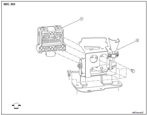
- Distance sensor
- Bracket
 Front
Front
Removal and Installation
REMOVAL
- Remove the front bumper fascia. Refer to EXT-20, "Removal and Installation".
- Remove distance sensor bolts and the distance sensor.
CAUTION: Do not drop or shock distance sensor.
- Remove bolts and distance sensor bracket (if necessary).
INSTALLATION
Installation is in the reverse order of removal.
CAUTION: Perform additional service when replacing distance sensor. Refer to DAS-69, "Work Procedure".
SIDE CAMERA
Removal and Installation
REMOVAL
- Remove door mirror rear finisher (2). Refer to MIR-25, "Removal and Installation".
- Remove screws (A) and side camera (1).
 : Pawl
INSTALLATION
Installation is in the reverse order of removal.
CAUTION: Perform camera image calibration (if equipped with around view camera). Refer to AV-135, "CALIBRATING CAMERA IMAGE (AROUND VIEW MONITOR) : Description".
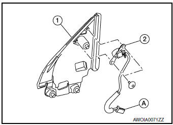
BSW INDICATOR
Removal and Installation
REMOVAL
- Remove the front door finisher. Refer to INT-15, "Removal and Installation".
- Release the door mirror corner finisher using a suitable tool. Refer to MIR-22, "Exploded View".
- Disconnect the harness connector (A), release the harness clip and remove the door mirror corner finisher (1).
- Remove screws and blind spot warning indicator (2).
INSTALLATION
Installation is in the reverse order of removal.
AROUND VIEW MONITOR CONTROL UNIT
Exploded View
- Around view monitor control unit
- Harness connector
Removal and Installation
REMOVAL
CAUTION: Before replacing around view monitor control unit, save or print current vehicle specification with CONSULT configuration before replacement. Refer to AV-288, "ADDITIONAL SERVICE WHEN REPLACING AROUND VIEW MONITOR CONTROL UNIT : Work Procedure".
- Remove glove box assembly. Refer to IP-23, "Removal and Installation".
- Remove around view monitor control unit screws.
- Disconnect the harness connector from the around view monitor control unit and remove.
INSTALLATION
Installation is in the reverse order of removal.
CAUTION:
- Replace the around view monitor control unit if it has been dropped or sustained an impact.
- When replacing around view monitor control unit, you must
perform "After Replace ECU" with CONSULT.
Refer to AV-288, "ADDITIONAL SERVICE WHEN REPLACING AROUND VIEW MONITOR CONTROL UNIT : Work Procedure".
NOTE: Perform camera image calibration. Refer to AV-292, "CALIBRATING CAMERA IMAGE (AROUND VIEW MONITOR) : Work Procedure".
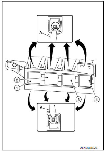
WARNING SYSTEMS SWITCH
Removal and Installation
REMOVAL
- Remove the instrument lower panel LH. Refer to IP-14, "Exploded View".
- Remove the screws (A) that retain the upper (1) and lower (2) switch carriers.
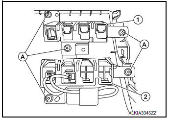
- Release pawls using a suitable tool (A), then remove the warning
systems switch (2) from the lower switch carrier.
(1): Blank
(3): AWD LOCK switch (if equipped)
(4): Hill descent control switch (if equipped)
INSTALLATION
Installation is in the reverse order of removal.
WARNING SYSTEMS BUZZER
Exploded View
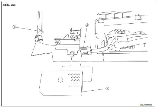
- Instrument lower panel LH
- Warning systems buzzer
- Harness connector
 Pawl
Pawl
Removal and Installation
REMOVAL
- Remove instrument lower panel LH. Refer to IP-14, "Exploded View".
- Remove warning systems buzzer from bracket on the back of the instrument lower panel LH.
INSTALLATION
Installation is in the reverse order of removal.
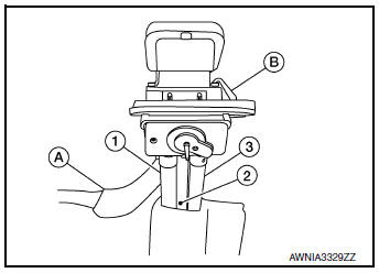
REAR VIEW CAMERA
Removal and Installation
REMOVAL
- Remove the back door outer finisher. Refer to EXT-50, "Removal and Installation".
- Disconnect washer tubes (1,3) and air tube (2) (if equipped).
- Release pawl (B), disconnect harness connector (A) from rear view camera and remove.
INSTALLATION
Installation is in the reverse order of removal.
REAR VIEW CAMERA WASHER MOTOR
Exploded View
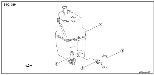
- Front and rear wiper motor
- Seal
- Rear view camera washer motor
- Washer tank
 Front
Front
Removal and Installation
REMOVAL
- Drain the washer fluid.
- Remove the front under cover. Refer to EXT-16, "Exploded View".
- Remove engine side cover. Refer to EXT-28, "FENDER PROTECTOR : Exploded View".
- Disconnect the harness connector from the rear view camera washer motor.
- Disconnect the washer tube from the rear view camera washer motor.
- Remove the rear view camera washer motor.
- Remove the washer tank seal (if necessary).
INSTALLATION
Installation is in the reverse order of removal.
CAUTION: Add water to the top of washer tank inlet after installing. Check that no leaks exist.
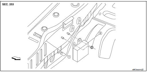
REAR VIEW CAMERA AIR PUMP MOTOR
Exploded View

- Rear floor
- Rear view camera air pump motor
- Bracket
Front
Removal and Installation
REMOVAL
- Remove the rear bumper fascia under cover (LH). Refer to EXT-20, "Exploded View".
- Disconnect the air tubes from the rear view camera air pump motor.
- Disconnect the harness connector from the rear view camera air pump motor.
- Remove bolts and rear view camera air pump motor.
- Remove nuts and remove bracket (if necessary).
INSTALLATION
Installation is in the reverse order of removal.
REAR VIEW CAMERA WASHER CONTROL UNIT
Exploded View
- Body panel
- Rear view camera washer control unit
Removal and Installation
REMOVAL
- Remove the luggage rear plate. Refer to INT-37, "LUGGAGE REAR PLATE : Removal and Installation".
- Disconnect the harness connector from the rear view camera washer control unit.
- Remove the rear view camera washer control unit nuts.
- Remove the rear view camera washer control unit.
INSTALLATION
Installation is in the reverse order of removal.
 Symptom diagnosis
DRIVER ASSISTANCE SYSTEM SYMPTOMS
Symptom Table
LANE DEPARTURE WARNING SYSTEM SYMPTOMS
NOTE:
Refer to the following the operation condition of the Lane Departure Warning
system.
Lane D ...
 Chassis control
...
Other materials:
Parking brake shoe
Exploded View
Back plate
Parking brake shoe
Brake strut
Return spring
Spring
Return spring to brake strut
Adjuster
Toggle lever
Anti-rattle pin
: Apply PBC (Poly Butyl
Cuprysil) grease or silicone-based grease
Removal and Installation
REMOVAL
WARNING ...
P0462, P0463 fuel level sensor
DTC Description
DTC DETECTION LOGIC
This diagnosis indicates the former, to detect open or short circuit
malfunction.
DTC No.
CONSULT screen terms
(Trouble diagnosis content)
DTC detecting condition
P0462
FUEL LEVL SEN/CIRC
(Fuel level sensor ″A″ circu ...
Symptom diagnosis
HEATER AND AIR CONDITIONING SYSTEM CONTROL SYMPTOMS
Symptom Table
SYMPTOM TABLE
Symptom
Reference Page
A/C system does not come on.
Go to Trouble Diagnosis Procedure for A/C System.
HAC-166, "FRONT
A/C CONTROL : Diagnosis
Procedure"
Air ou ...
