Nissan Rogue Service Manual: Basic inspection
DIAGNOSIS AND REPAIR WORKFLOW
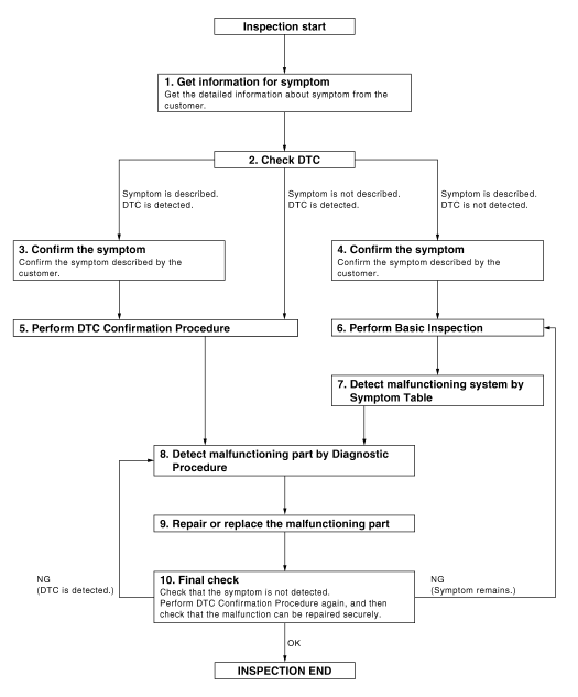
Work Flow
OVERALL SEQUENCE
DETAILED FLOW
1. GET INFORMATION FOR SYMPTOM
Get the detailed information from the customer about the symptom (the condition and the environment when the incident/malfunction occurred).
>> GO TO 2.
2. CHECK DTC
- Check DTC.
- Perform the following procedure if DTC is displayed.
- Record DTC and freeze frame data (Print them out with CONSULT.)
- Erase DTC.
- Study the relationship between the cause detected by DTC and the symptom described by the customer.
- Check related service bulletins for information.
Is any symptom described and any DTC detected? Symptom is described, DTC is displayed>>GO TO 3.
Symptom is described, DTC is not displayed>>GO TO 4.
Symptom is not described, DTC is displayed>>GO TO 5.
3. CONFIRM THE SYMPTOM
Confirm the symptom described by the customer.
Connect CONSULT to the vehicle in ŌĆ£DATA MONITORŌĆØ mode and check real time diagnosis results.
Verify relation between the symptom and the condition when the symptom is detected.
>> GO TO 5.
4. CONFIRM THE SYMPTOM
Confirm the symptom described by the customer.
Connect CONSULT to the vehicle in ŌĆ£DATA MONITORŌĆØ mode and check real time diagnosis results.
Verify relation between the symptom and the condition when the symptom is detected.
>> GO TO 6.
5. PERFORM DTC CONFIRMATION PROCEDURE
Perform DTC Confirmation Procedure for the displayed DTC, and then check that DTC is detected again.
At this time, always connect CONSULT to the vehicle, and check diagnostic results in real time.
If two or more DTCs are detected, refer to BCS-47, "DTC Inspection Priority Chart" (with Intelligent Key system) or BCS-107, "DTC Inspection Priority Chart" (without Intelligent Key system) and determine trouble diagnosis order.
NOTE:
- Freeze frame data is useful if the DTC is not detected.
- Perform Component Function Check if DTC Confirmation Procedure
is not included in Service Manual. This
simplified check procedure is an effective alternative though DTC cannot be
detected during this check.
If the result of Component Function Check is NG, it is the same as the detection of DTC by DTC Confirmation Procedure.
Is DTC detected? YES >> GO TO 8.
NO >> Refer to GI-41, "Intermittent Incident".
6. PERFORM BASIC INSPECTION
Perform DEF-19, "Work Flow".
>> GO TO 7
7. DETECT MALFUNCTIONING SYSTEM BY SYMPTOM TABLE
Detect malfunctioning system according to DEF-6, "System Description" based on the confirmed symptom in step 4, and determine the trouble diagnosis order based on possible causes and symptom.
>> GO TO 8.
8. DETECT MALFUNCTIONING PART BY DIAGNOSTIC PROCEDURE
Inspect according to Diagnostic Procedure of the system.
NOTE: The Diagnostic Procedure described based on open circuit inspection. A short circuit inspection is also required for the circuit check in the Diagnostic Procedure.
Is malfunctioning part detected? YES >> GO TO 9.
NO >> Check voltage of related BCM terminals using CONSULT.
9. REPAIR OR REPLACE THE MALFUNCTIONING PART
- Repair or replace the malfunctioning part.
- Reconnect parts or connectors disconnected during Diagnostic Procedure again after repair and replacement.
- Check DTC. If DTC is displayed, erase it.
>> GO TO 10.
10. FINAL CHECK
When DTC was detected in step 2, perform DTC Confirmation Procedure or Component Function Check again, and then check that the malfunction have been repaired securely.
When symptom was described from the customer, refer to confirmed symptom in step 3 or 4, and check that the symptom is not detected.
Does the symptom reappear? YES (DTC is detected)>>GO TO 8.
YES (Symptom remains)>>GO TO 6.
NO >> Inspection End.
 Wiring diagram
REAR WINDOW DEFOGGER SYSTEM
Wiring Diagram
...

Other materials:
Illumination
Wiring Diagram
...
Preparation
Commercial Service Tool
Tool name
Description
Ball joint remover
Removing wheel stud
Power tools
Loosening nuts, screws, and bolts
...
Air flow charts
The following charts show the button and dial
positions for MAXIMUM AND QUICK heating,
cooling or defrosting. The air recirculation indicator
should always be in the OFF position
for heating and defrosting.
...
