Nissan Rogue (T33) 2021-Present Service Manual: Removal and Installation :: Spiral Cable
Exploded View
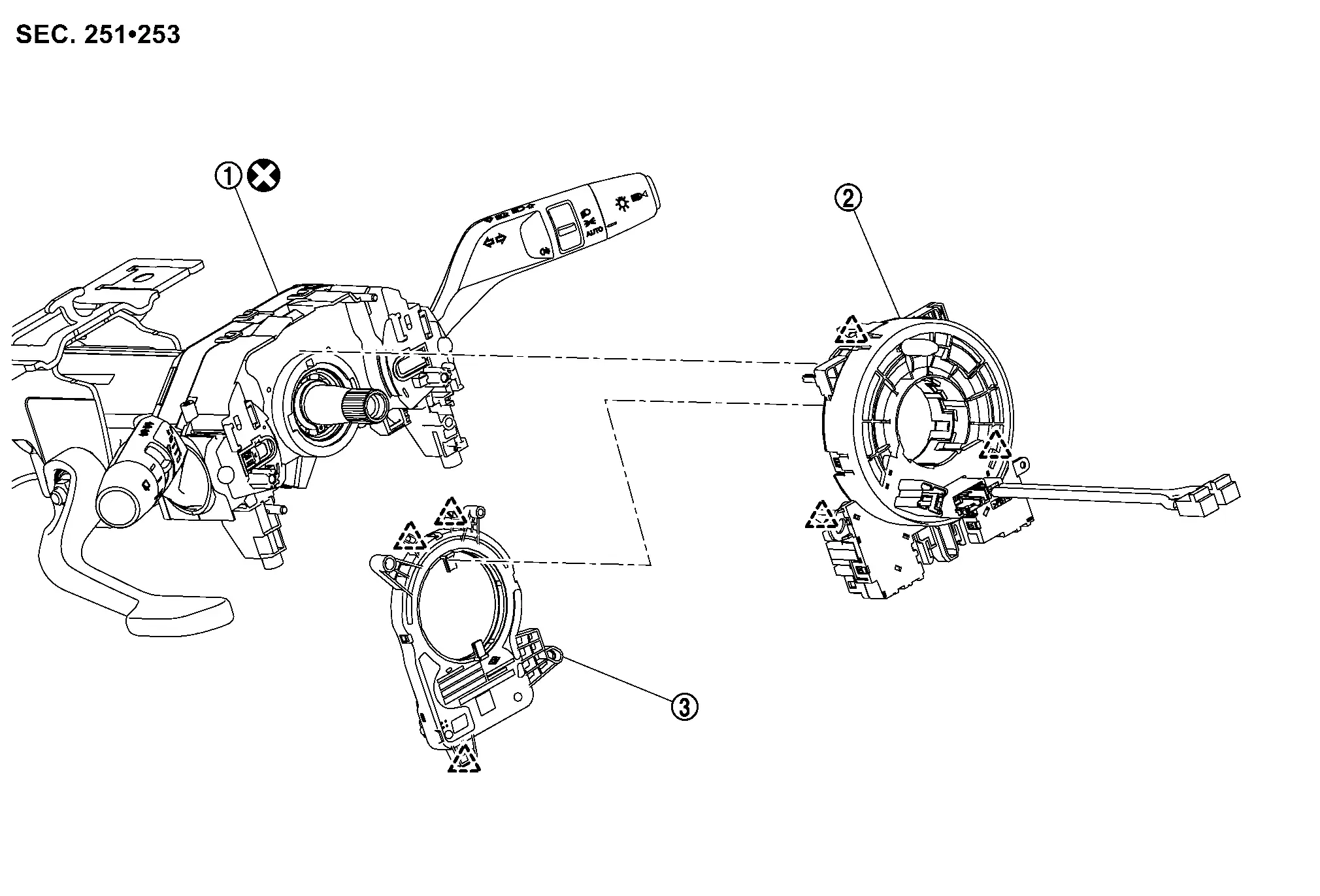
 |
Combination switch |  |
Spiral cable |  |
Steering angle sensor |
 |
: Pawl | ||||
 |
: Always replace after every disassembly. | ||||
Removal and Installation
WARNING:
Always observe the following items for preventing accidental activation.
-
Never use air tools or electric tools for servicing.
REMOVAL
Remove steering wheel. Refer to Removal and Installation.
Remove steering column cover. Refer to Removal and Installation.
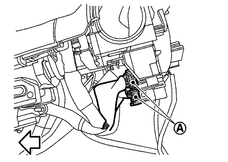
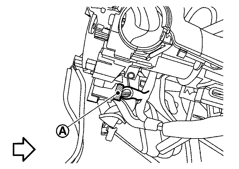
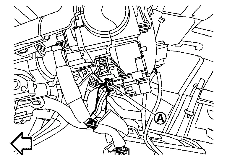
Disconnect spiral cable body side harness connectors  .
.
-
Left side

: Nissan Ariya Vehicle front -
Right side (with steering heater models)
: Nissan Ariya Vehicle front
Disconnect steering angle sensor body side harness connector .
| : Nissan Ariya Vehicle front |
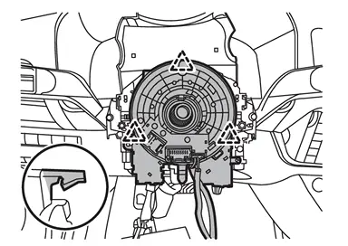
Disengage spiral cable fixing pawls, and then remove spiral cable with steering angle sensor.
|
: Pawl |
Disengage steering angle sensor fixing pawls, and then remove steering angle sensor from spiral cable.
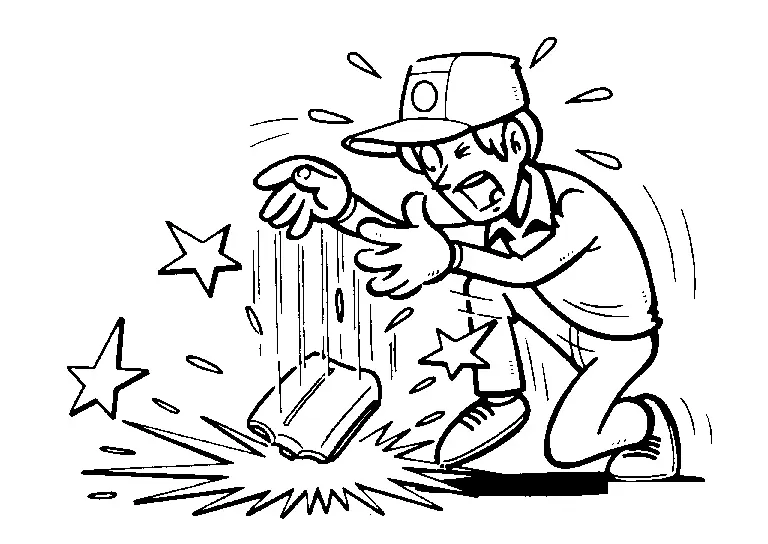
CAUTION:
-
To prevent damage to the parts, never impact the spiral cable.
-
Replace spiral cable if it is dropped or sustains an impact.
-
To prevent damage to the parts, never disassemble the spiral cable.
-
To prevent damage to the parts, never apply lubricant to the spiral cable.
-
To prevent damage to the parts, never allow oil, grease, detergent, or water to come in contact with the spiral cable.
INSTALLATION
Note the following items, and then install in the reverse order of removal.
CAUTION:
-
Always replace combination switch with a new one when spiral cable is removed. Refer to Removal and Installation.
-
After installation is completed, perform steering torque calibration. Refer to Work Procedure.
-
The spiral cable may snap during steering operation if the cable is installed in an improper position.
-
When install spiral cable, set the neutral position following procedure below.
 NOTE:
NOTE:
If you buy the new parts, no need to set the neutral position because its has been set the neutral position.
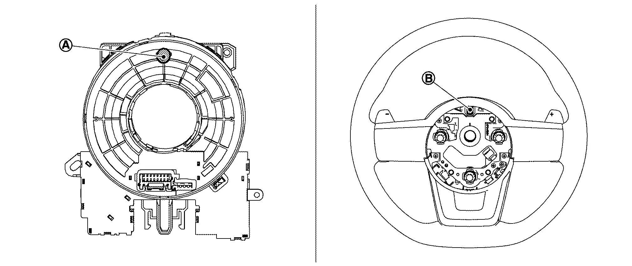
Install steering angle sensor to spiral cable.
CAUTION:
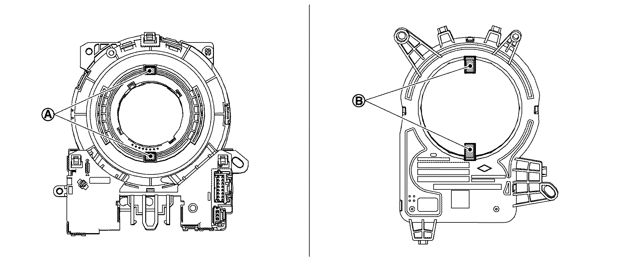
When installing, align (A) of spiral cable and (B) of steering angle sensor.
Set the neutral position.Carefully turn spiral cable clockwise to the end position.
CAUTION:
Never turn spiral cable powerfully where the end position.
Turn counterclockwise (about 2 and a half turns) and stop turning where the part of (B) matching mark is fit and which the clear window (A) appear yellow mark.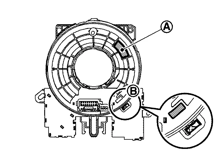
Install spiral cable into combination switch by fixing pawls.
Connect body harness to spiral cable and steering angle sensor.
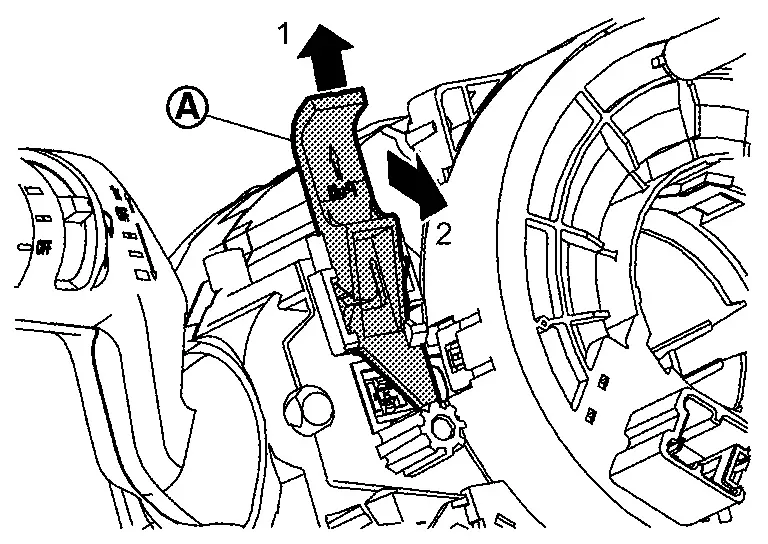
Remove lock pin (A) of combination switch according to numerical order 1→2 indicated by arrows as shown in figure.
Install steering column cover. Refer to Removal and Installation.
Install steering wheel. Refer to Removal and Installation.
CAUTION:
When install steering wheel, set locate pin (A) of spiral cable and locate hole (B) of steering wheel.
Other materials:
P023a Charge Air Cooler Cooling Electric Water Pump
DTC Description
DTC DETECTION LOGIC DTC
CONSULT screen terms
(Trouble diagnosis content)
DTC detection condition
P023A
00
Charged air cooler coolant pump
(Charge Air Cooler Coolant Pump Control Circuit/Open)
Diagnosis condition
Engine running at idle
Warm-up con ...
System Description. System. Power Window System
Power Window System
System Description
SYSTEM DIAGRAM Component Function
Front door switch
Detects front door open/close condition and transmits door switch signal to BCM.
BCM
Controls power window relay.
Controls retained power function.
Power window main switch ...
Ignition Signal
Component Function Check
INSPECTION START
Turn ignition switch OFF, and restart engine.
Does the engine start?
YES-1>>
With CONSULT: GO TO 2.
YES-2>>
Without CONSULT: GO TO 3.
NO>>
Refer to Diagnosis Procedure.
CHECK IGNITION SIGNAL FUNCTION-1
With CONSULT
Perfor ...