Nissan Rogue (T33) 2021-Present Service Manual: Ignition Signal
Component Function Check
INSPECTION START
Turn ignition switch OFF, and restart engine.
Does the engine start?
YES-1>>With CONSULT: GO TO 2.
YES-2>>Without CONSULT: GO TO 3.
NO>>Refer to Diagnosis Procedure.
CHECK IGNITION SIGNAL FUNCTION-1
 With CONSULT
-
Perform ÔÇťPOWER BALANCEÔÇŁ in ÔÇťACTIVE TESTÔÇŁ mode of ÔÇťENGINEÔÇŁ with CONSULT.
-
Check that each circuit produces a momentary engine speed drop.
Is the inspection result normal?
YES>>INSPECTION END
NO>>Refer to Diagnosis Procedure.
CHECK IGNITION SIGNAL FUNCTION-2
 Without CONSULT
-
Let engine idle.
-
Read the voltage signal between ECM harness connector terminals with an oscilloscope.
ECM Voltage signal + Ôłĺ Connector Terminal Connector Terminal F72 36 E21 160 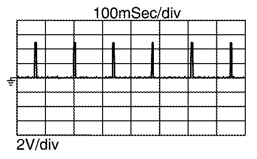
44 36  NOTE:
NOTE:
The pulse cycle changes depending on rpm at idle.
Is the inspection result normal?
YES>>INSPECTION END
NO>>Refer to Diagnosis Procedure.
Diagnosis Procedure
CHECK IGNITION COIL POWER SUPPLY
-
Turn ignition switch OFF.
-
Disconnect ignition coil harness connector.
-
Turn ignition switch ON.
-
Check the voltage between ignition coil harness connector and ground.
+ Ôłĺ Voltage Ignition coil Cylinder Connector Terminal 1 F47 3 Ground Battery voltage 2 F46 3 F48
Is the inspection result normal?
YES>>GO TO 5.
NO>>GO TO 2.
CHECK FUSE
-
Turn ignition switch OFF.
-
Pull out No. 79 fuse (15 A) and check that the fuse is not blowing.
Is the inspection result normal?
YES>>GO TO 3.
NO>>Replace the fuse after repairing the applicable circuit.
CHECK IGNITION COIL POWER SUPPLY CIRCUIT
-
Turn ignition switch OFF.
-
Disconnect IPDM E/R harness connector.
-
Check the continuity between IPDM E/R harness connector and ignition coil harness connector.
Ignition coil IPDM E/R Continuity Cylinder Connector Terminal Connector Terminal 1 F47 3 F35 66 Existed 2 F46 3 F48 -
Check harness for short to ground and to power.
Is the inspection result normal?
YES>>GO TO 4.
NO>>Repair or replace error-detected parts.
CHECK IPDM E/R POWER SUPPLY AND GROUND CIRCUIT
Check IPDM E/R power supply and ground circuit. Refer to Diagnosis Procedure.
Is the inspection result normal?
YES>>Replace IPDM E/R. Refer to Removal and Installation.
NO>>Repair or replace error-detected parts.
CHECK IGNITION COIL GROUND
-
Turn ignition switch OFF.
-
Check the continuity between ignition coil harness connector and ground.
+ Ôłĺ Continuity Ignition coil Cylinder Connector Terminal 1 F47 2 Ground Existed 2 F46 3 F48
Is the inspection result normal?
YES>>GO TO 6.
NO>>Repair or replace error-detected parts.
CHECK IGNITION SIGNAL CIRCUIT
-
Disconnect ECM harness connector.
-
Check the continuity between ignition coil harness connector and ECM harness connector.
Ignition coil ECM Continuity Cylinder Connector Terminal Connector Terminal 1 F47 1 F72 36 Existed 2 F46 44 3 F48 33 -
Also check harness for short to ground and to power.
Is the inspection result normal?
YES>>GO TO 7.
NO>>Repair or replace error-detected parts.
CHECK IGNITION COIL WITH POWER TRANSISTOR
Check ignition coil with power transistor. Refer to Component Inspection.
Is the inspection result normal?
YES>>Check intermittent incident. Refer to Intermittent Incident.
NO>>Replace malfunctioning ignition coil with power transistor. Refer to Removal and Installation.
Other materials:
P023a Charge Air Cooler Cooling Electric Water Pump
DTC Description
DTC DETECTION LOGIC DTC
CONSULT screen terms
(Trouble diagnosis content)
DTC detection condition
P023A
00
Charged air cooler coolant pump
(Charge Air Cooler Coolant Pump Control Circuit/Open)
Diagnosis condition
Engine running at idle
Warm-up con ...
Dtc/circuit Diagnosis. B203d-14 Inside Antenna
DTC Description
DTC DETECTION LOGIC DTC No.
CONSULT screen items
(Trouble diagnosis content) DTC detecting condition
B203D-14
Inside antenna
(Inside antenna)
Diagnosis condition
Work supports ÔÇťInside/outside antenna diagnosisÔÇŁ: activated
Signal (terminal)
Inside key an ...
Can Gateway. Precaution. Precautions
Precautions
PRECAUTIONS FOR SUPPLEMENTAL RESTRAINT SYSTEM (SRS) AIR BAG AND SEAT BELT PRE-TENSIONER
: Precautions
The Supplemental Restraint System such as ÔÇťAIR BAGÔÇŁ and ÔÇťSEAT BELT
PRE-TENSIONERÔÇŁ, used along with a front seat belt, helps to reduce the
risk or severit ...