Nissan Rogue (T33) 2021-Present Service Manual: Removal and Installation :: Sonar Sensor
Front
Exploded View
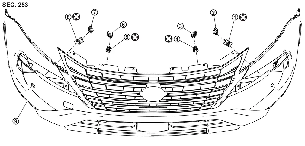
| 1. | Front sonar sensor LH outer holder | 2. | Front sonar sensor LH outer | 3. | Front sonar sensor LH inner |
| 4. | Front sonar sensor LH inner holder | 5. | Front sonar sensor RH inner holder | 6. | Front sonar sensor RH inner |
| 7. | Front sonar sensor RH outer | 8. | Front sonar sensor RH outer holder | 9. | Front bumper fascia |
 |
:Always replace after every disassembly. | ||||
Removal and Installation
REMOVAL
When removing the front sonar sensor inner, remove the front bumper. Refer to Removal and Installation.
Disconnect connector of the sonar sensor.
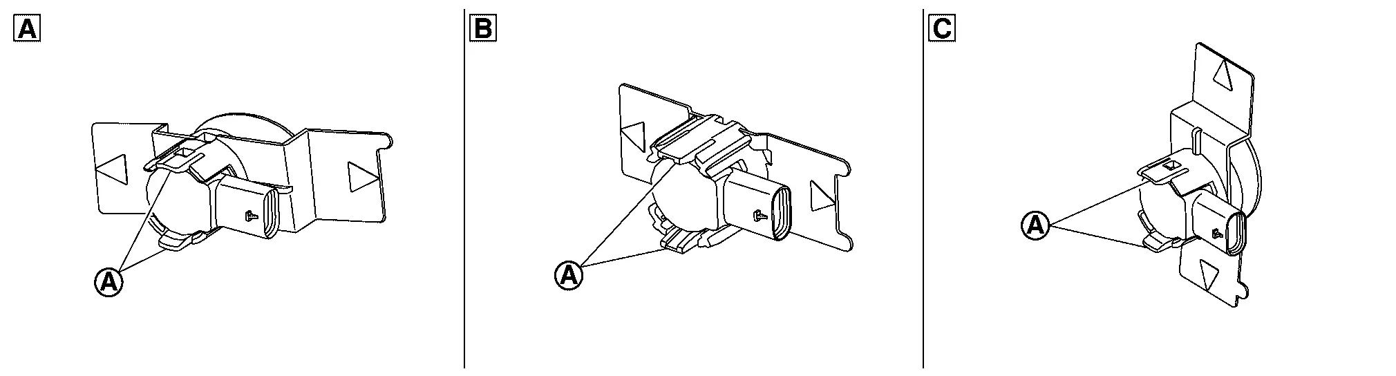
Unhook the pawls (A) to remove the sonar sensor (1) from the sensor holder (2).
| A | Front sonar sensor outer | B | Front sonar sensor inner | ||
Remove the sensor holder from the front bumper.
 NOTE:
NOTE:
Remove the front bumper, when remove the sensor holder.
INSTALLATION
CAUTION:
-
Check sonar sensor packing for damage before installation.
-
Check that the packing is properly installed to the sonar sensor.
-
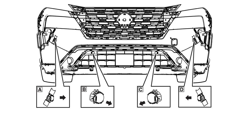
Install it so that the connector of the sensor turns to the arrow direction of the figure.
A Front sonar sensor LH side B Front sonar sensor LH inner C Front sonar sensor RH inner D Front sonar sensor RH side 
: Connector direction
-
Install in the reverse order of removal when install only the sensor.
-
Follow the procedure below when replace the sensor holder.
-
Install sonar sensor to sensor holder.
-
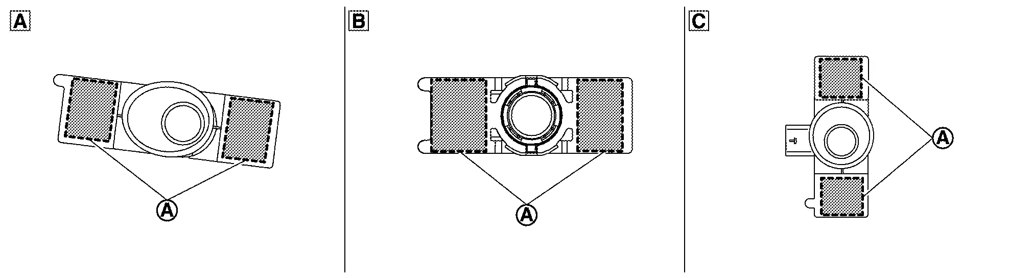
Degrease and clean the inner side of the bumper fascia base line and then apply primer (3M K500,K520 or equivalent) on the sensor holder installing face, which is shown as (A) on the figure.
A Front sonar sensor LH side CAUTION:
Never apply two coats of primer. Applying two coats or more of primer results in excessively thick film and this may allow the sensor holder to come off from primer under exfoliation.
-
Dry the primer for more than 3 minutes and peel off the double sided tape releasing paper (film) and then taking precautions not to contact the bumper with the double sided tape ((A) on the figure), bend the sensor holder to the arrow direction as shown on the figure (
 ).
).A Front sonar sensor LH side CAUTION:
Primer drying time depends on temperature and therefore confirm that primer has dried before bending the sonar holder.
-
Match the sonar sensor (A) part shown on the figure, to the sensor installing hole of the bumper fascia.
A Front sonar sensor LH side -
Remove the sensor from the sensor holder and press the adhesion face ((A) part on figure) throughout with your thumb for more than 2 seconds and pressure bond the sensor holder [Target pressure: 50 N (5.1kg, 11.3 lb)].
A Front sonar sensor LH side CAUTION:
-
When the temperature is less than 15°C (59°F), use a drier etc., to warm the adhesion face and proceed the work.
-
After installing the sensor holder, leave it at least for 2 - 3 hours.
-
-
Install the sensor to the sensor holder.
-
Shake the (A) part of the sensor holder shown on the figure up and down and then right and left to confirm that the holder has been installed (bonded) firmly.
A Front sonar sensor LH side B Front sonar sensor LH inner -
Connect connector to the sonar sensor.
-
Install the front bumper. Refer to Removal and Installation.
Rear
Exploded View
Without Side Sensor
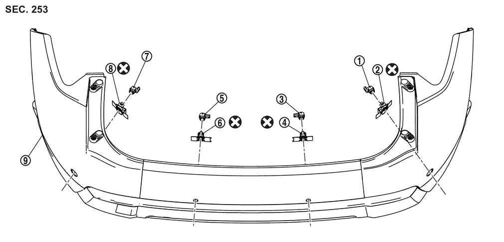
| 1. | Rear sonar sensor RH outer holder | 2. | Rear sonar sensor RH outer | 3. | Rear sonar sensor RH inner |
| 4. | Rear sonar sensor RH inner holder | 5. | Rear sonar sensor LH inner holder | 6. | Rear sonar sensor LH inner |
| 7. | Rear sonar sensor LH outer | 8. | Rear sonar sensor LH outer holder | 9. | Rear bumper fascia |
|
:Always replace after every disassembly. | ||||
With Side Sensor
| 1. | Rear sonar sensor RH side holder | 2. | Rear sonar sensor RH side | 3. | Rear sonar sensor RH outer holder |
| 4. | Rear sonar sensor RH outer | 5. | Rear sonar sensor RH inner | 6. | Rear sonar sensor RH inner holder |
| 7. | Rear sonar sensor LH inner holder | 8. | Rear sonar sensor LH inner | 9. | Rear sonar sensor LH outer |
| 10. | Rear sonar sensor LH outer holder | 11. | Rear sonar sensor LH side | 12. | Rear sonar sensor LH side holder |
| 13. | Rear bumper fascia | — | — | — | — |
|
:Always replace after every disassembly. | ||||
Removal and Installation
REMOVAL
Remove the rear bumper. Refer to Removal and Installation.
Disconnect connector of the sonar sensor.
Unhook the pawls (A) to remove the sonar sensor (1) from the sensor holder (2).
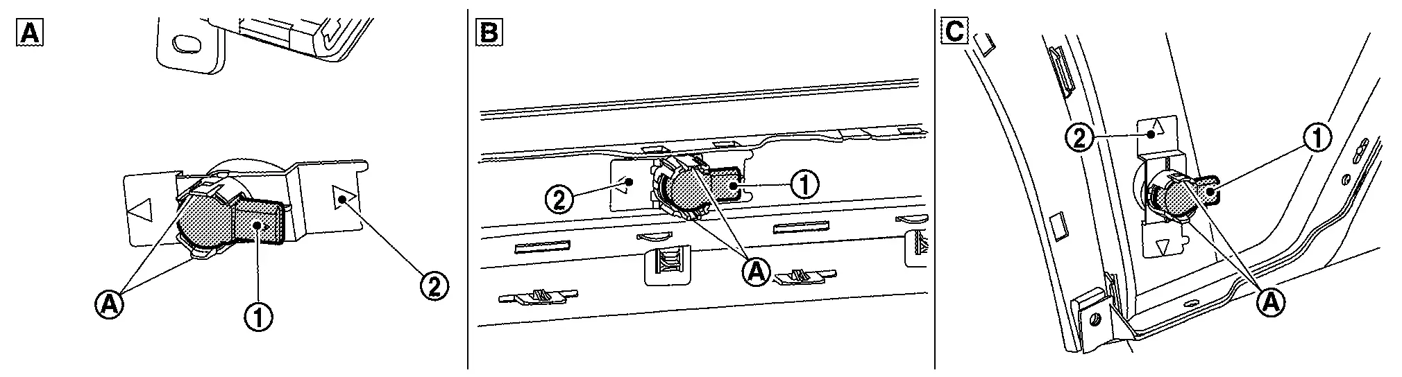
| A | Rear sonar sensor outer | B | Rear sonar sensor inner | C | Rear sonar sensor side |
Remove the sensor holder from the rear bumper.
INSTALLATION
CAUTION:
-
Check sonar sensor packing for damage before installation.
-
Check that the packing is properly installed to the sonar sensor.
-
Install it so that the connector of the sensor turns to the arrow direction of the figure.
Sensor Layout
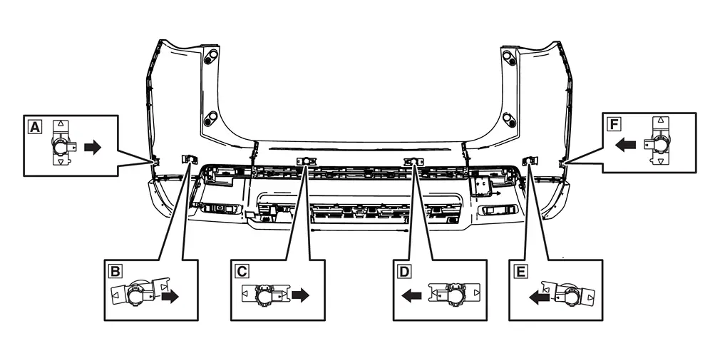
A Rear sonar sensor RH side B Rear sonar sensor RH outer C Rear sonar sensor RH inner D Rear sonar sensor LH inner E Rear sonar sensor LH outer F Rear sonar sensor LH side : Connector direction
-
Install in the reverse order of removal when install only the sensor.
-
Follow the procedure below when replace the sensor holder.
-
Install the sonar sensor to the sensor holder.
-
Degrease and clean the inner side of the bumper fascia base line and then apply primer (3M K500,K520 or equivalent) on the sensor holder installing face, which is shown as (A) on the figure.
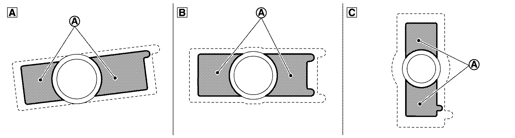
A Rear sonar sensor LH outer B Rear sonar sensor LH inner C Rear sonar sensor LH side CAUTION:
Never apply two coats of primer. Applying two coats or more of primer results in excessively thick film and this may allow the sensor holder to come off from primer under exfoliation.
-
Dry the primer for more than 3 minutes and peel off the double sided tape releasing paper (film) and then taking precautions not to contact the bumper with the double sided tape ((A) on the figure), bend the sensor holder to the arrow direction as shown on the figure (
).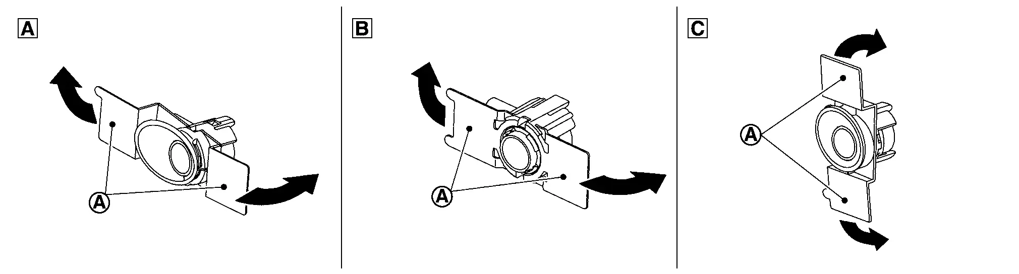
A Rear sonar sensor LH outer B Rear sonar sensor LH inner C Rear sonar sensor LH side CAUTION:
Primer drying time depends on temperature and therefore confirm that primer has dried before bending the sonar holder.
-
Match the sonar sensor (A) part shown on the figure, to the sensor installing hole of the bumper fascia.
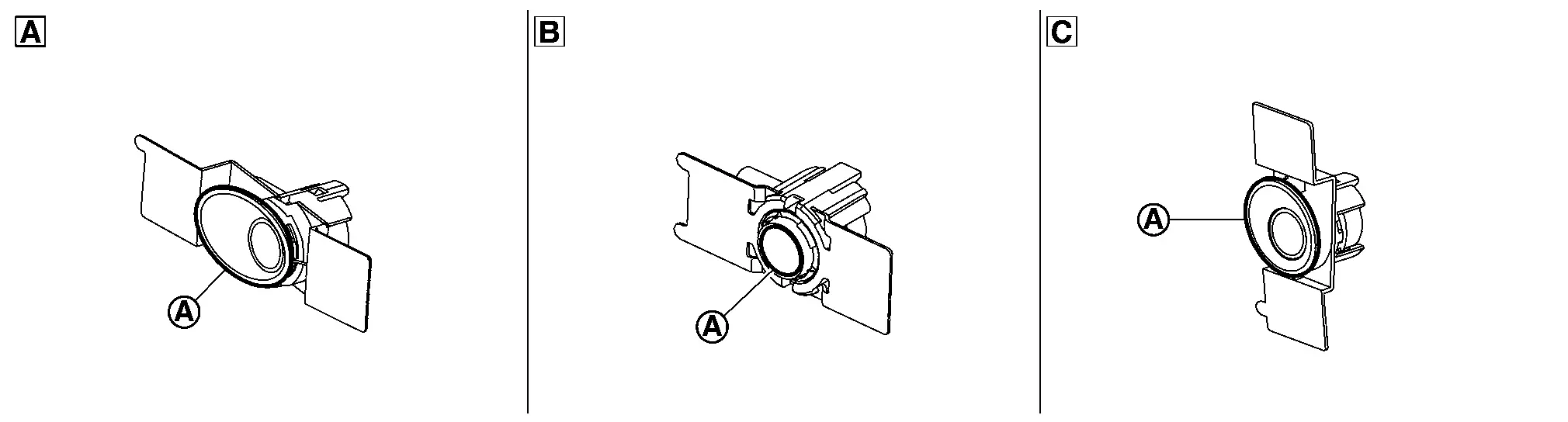
A Rear sonar sensor LH outer B Rear sonar sensor LH inner C Rear sonar sensor LH side -
Remove the sensor from the sensor holder and press the adhesion face ((A) part on figure) throughout with your thumb for more than 2 seconds and pressure bond the sensor holder [Target pressure: 50 N (5.1kg, 11.3 lb)].
A Rear sonar sensor LH outer B Rear sonar sensor LH inner C Rear sonar sensor LH side CAUTION:
-
When the temperature is less than 15°C (59°F), use a drier etc., to warm the adhesion face and proceed the work.
-
After installing the sensor holder, leave it at least for 2 - 3 hours.
-
-
Install the sensor to the sensor holder.
-
Shake the (A) part of the sensor holder shown on the figure up and down and then right and left to confirm that the holder has been installed (bonded) firmly.
A Rear sonar sensor LH outer B Rear sonar sensor LH inner C Rear sonar sensor LH side -
Connect connector to the sonar sensor.
-
Install the rear bumper. Refer to Removal and Installation.
Other materials:
B120e-55 Ipdm E/r
DTC Description
DTC DETECTION LOGIC DTC No.
CONSULT screen items
(Trouble diagnosis content) DTC detection condition
B120E-55
IPDM E/R
(Intelligent power distribution module engine room)
[NOT CONFIGURED]
Diagnosis condition
When ignition switch is ON
Signal (terminal)
â ...
System Description. System
System Description (Heated Steering Wheel)
SYSTEM DIAGRAMThe
heated steering wheel switch controls the heated steering wheel relay.
When the heated steering wheel switch is turned on, the heated steering
wheel relay is energized and the heated steering wheel system will
operate. The heated ...
Poste de conduite
Cette vue d’ensemble du poste de conduite du Nissan Rogue vous aide à repérer rapidement les commandes essentielles, que vous conduisiez en ville ou sur autoroute. Selon la finition de votre Nissan Rogue, certaines fonctions peuvent être présentes (signalées par *), notamment ProPILOT Assist ...