Nissan Rogue (T33) 2021-Present Service Manual: Removal and Installation :: Front Door Finisher
Exploded View
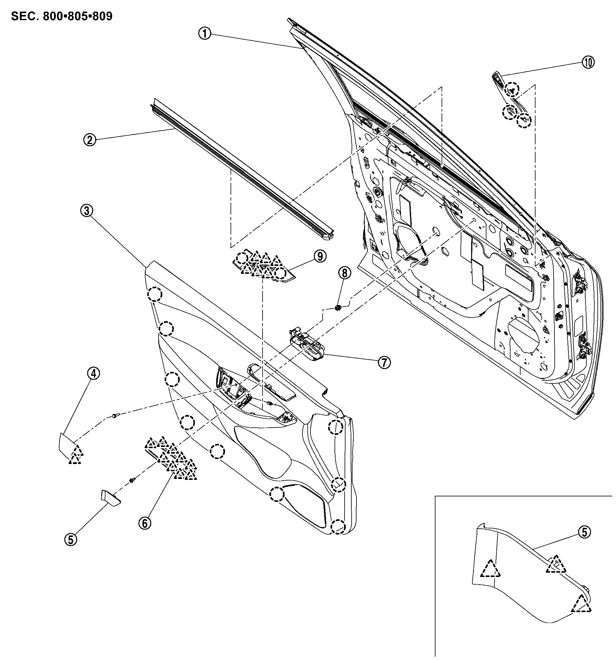
Driver side
 |
Front door panel |  |
Inside seal |  |
Front door finisher |
 |
Pull handle cap |  |
Inside handle cap |  |
Inside handle finisher |
 |
Inside handle |  |
Grommet |  |
Power window switch finisher |
 |
Door corner cover | ||||
 |
: Clip | ||||
 |
: Pawl | ||||
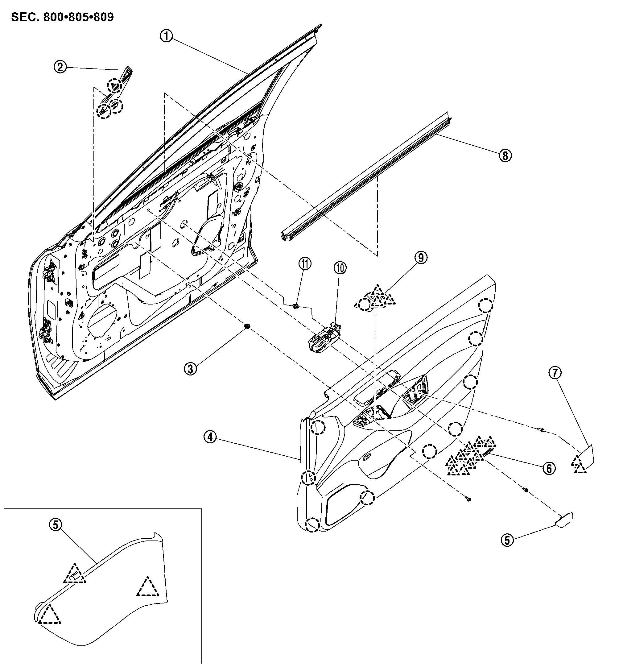
Passenger side
|
Front door panel | |
Door corner cover | |
Grommet |
|
Front door finisher | |
Inside handle cap | |
Inside handle finisher |
|
Pull handle cap | |
Inside seal | |
Power window switch finisher |
|
Inside handle |  |
Grommet | ||
|
: Clip | ||||
|
: Pawl | ||||
Removal and Installation
CAUTION:
Never damage the front door panel.
REMOVAL
Driver Side
Fully open driver side front door.
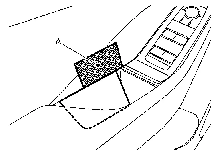
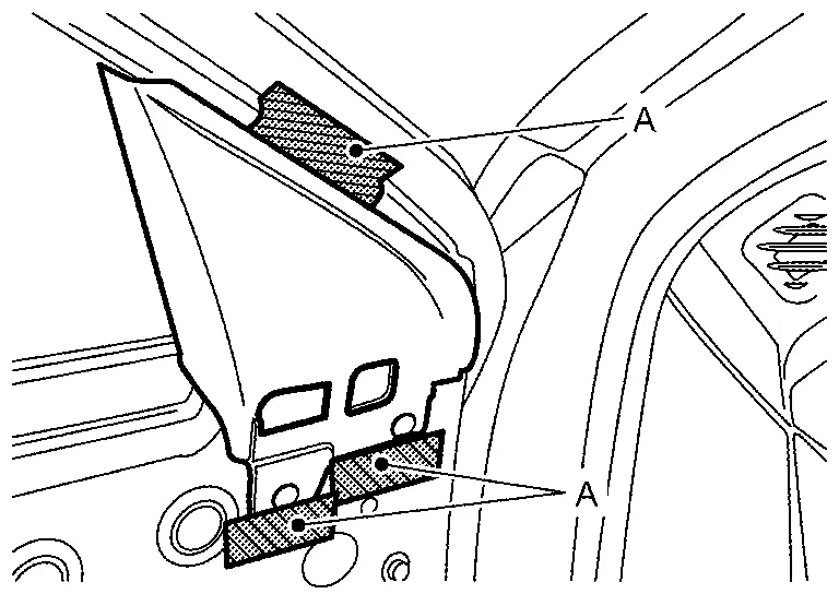
Remove pull handle cap.Apply protective tape (A) on front door finisher to protect it from damage.
|
: Pawl |
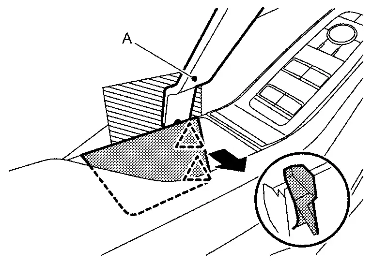
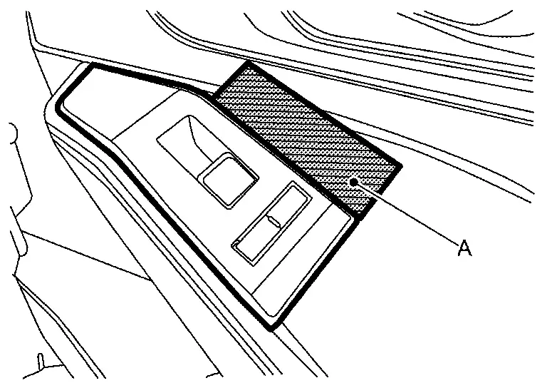
Remove power window switch finisher.Apply protective tapes (A) on front door finisher to protect it from damage.
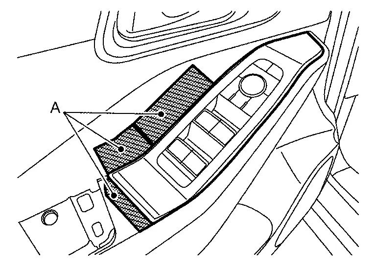
|
: Clip |
|
: Pawl |
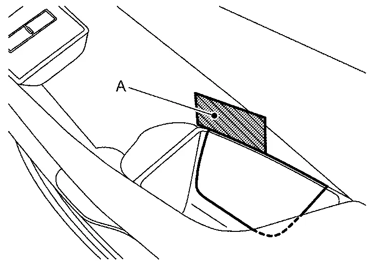
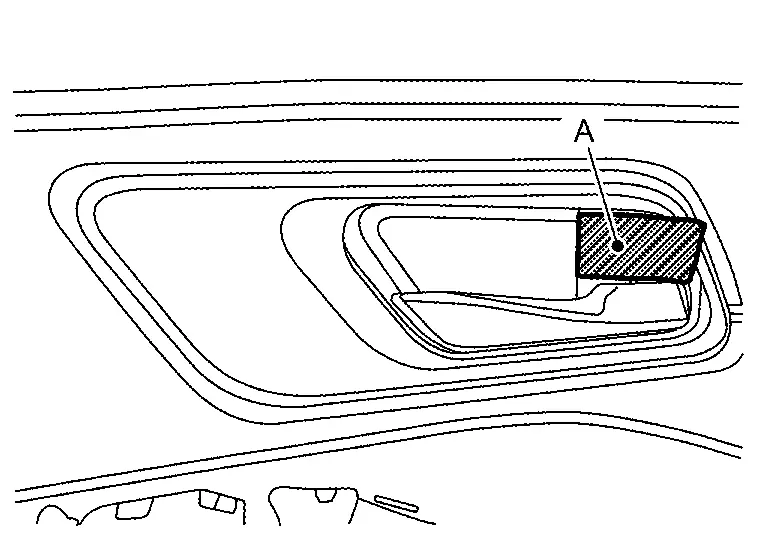
Remove inside handle cap.Apply protective tape (A) on inside handle to protect it from damage.
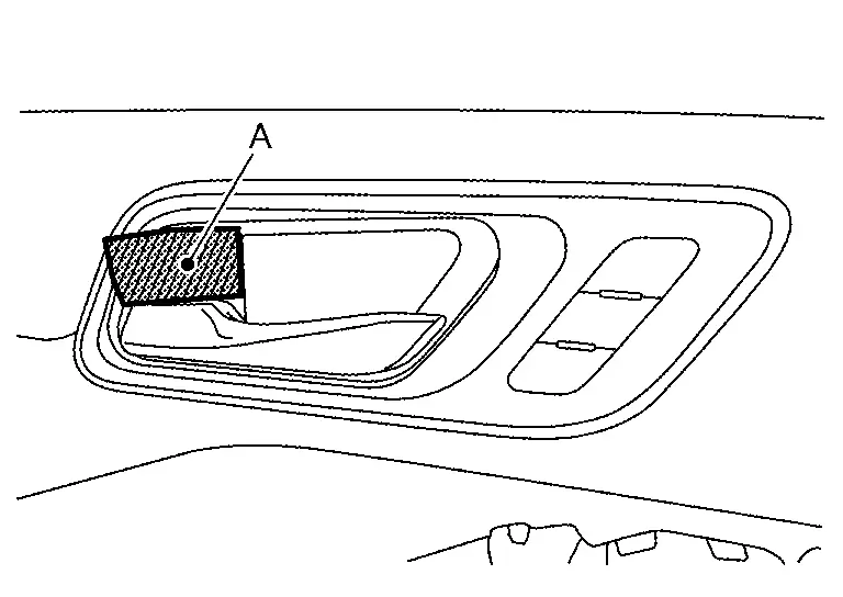
|
: Pawl |
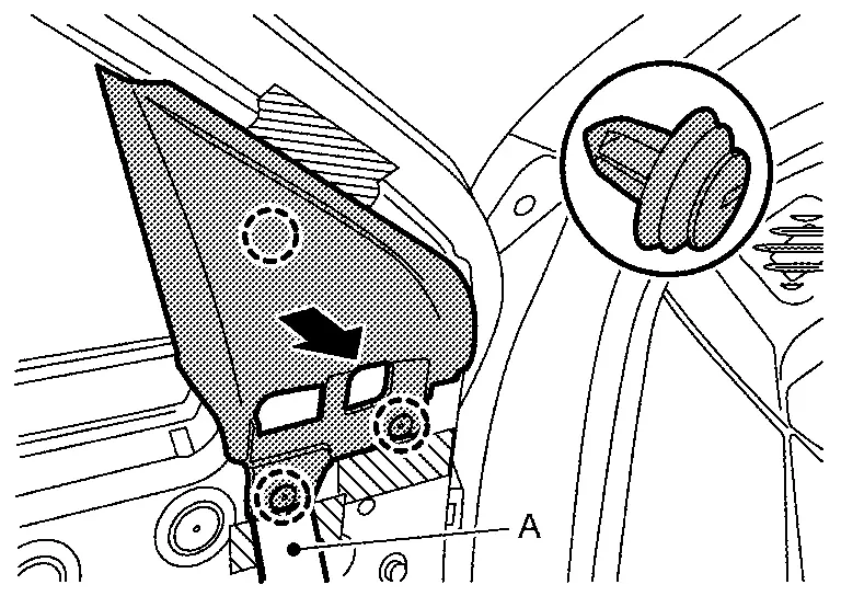
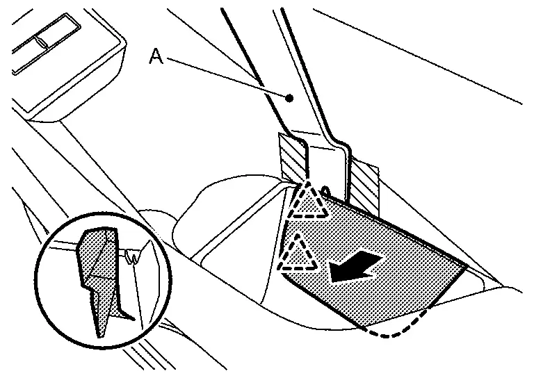
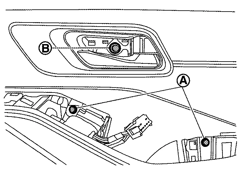
Remove front door finisher mounting screw (A) and mounting bolt (B).
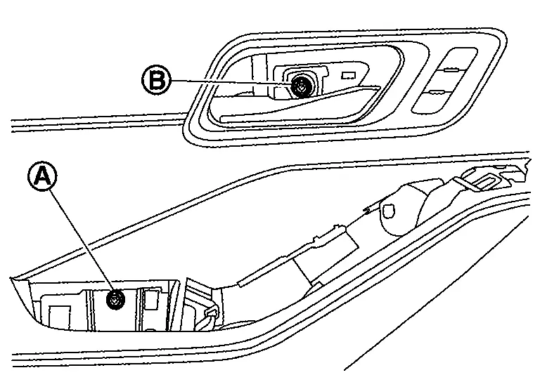
Apply protective tape (A) on front door panel to protect it from damage.
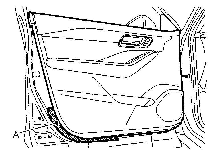
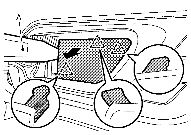
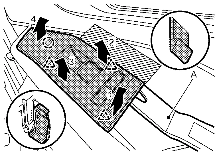
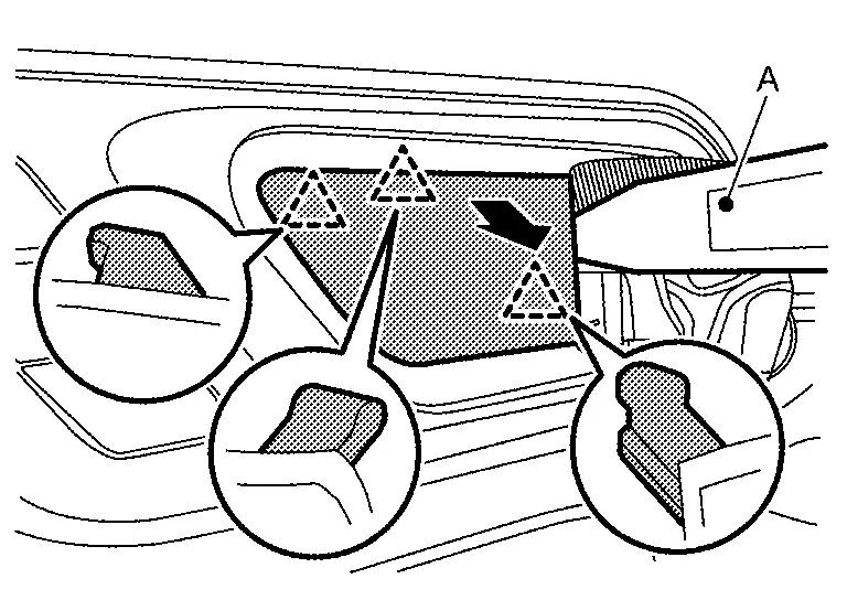
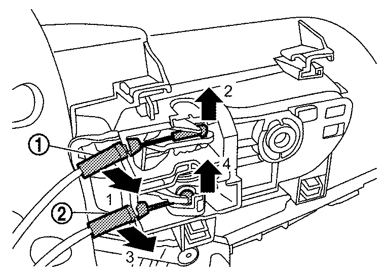
Disengage front door finisher fixing clips using a remover tool (A) according to numerical order 1→2 indicated by arrows as shown in the figure.
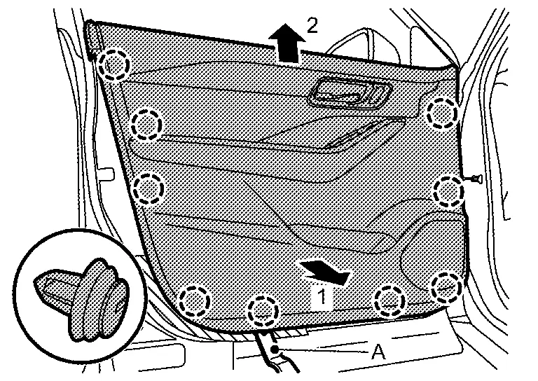
|
: Clip |
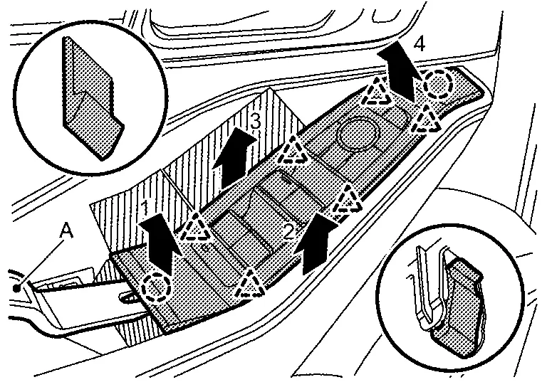
Disconnect lock knob cable (1) and inside handle cable (2) from inside handle according to numerical order 1→4 indicated by arrows as shown in the figure.
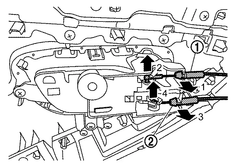
Disconnect harness connectors, and then remove front door finisher.
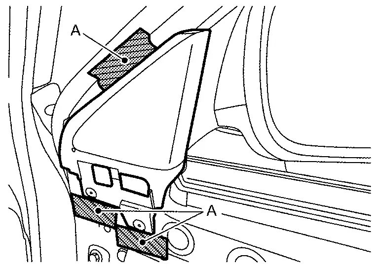
Remove door corner coverApply protective tapes (A) on front door panel to protect it from damage.
|
: Clip |
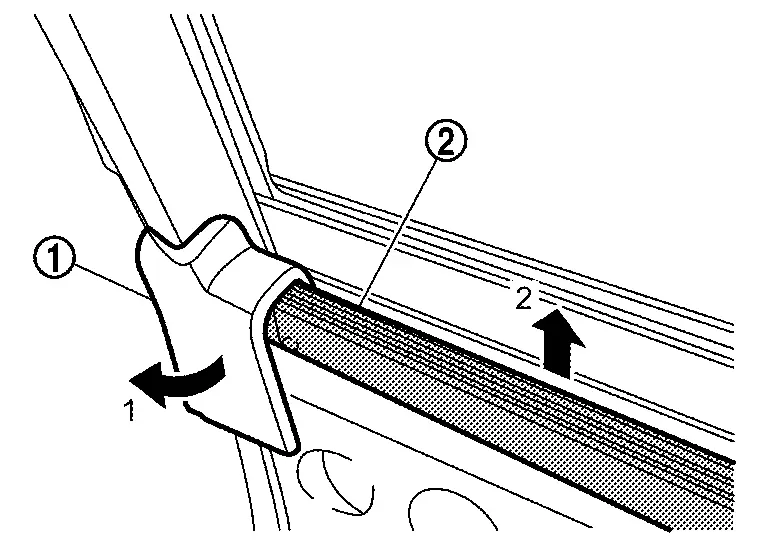
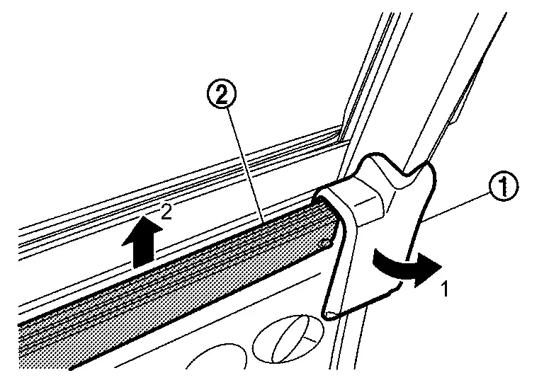
Disengage front door weather-strip (1), and then remove inside seal (2) according to numerical order 1→2 indicated by arrows as shown in the figure.
Passenger Side
Fully open passenger side front door.
Remove pull handle cap.Apply protective tape (A) on front door finisher to protect it from damage.
|
: Pawl |
Remove power window switch finisher.Apply protective tape (A) on front door finisher to protect it from damage.
|
: Clip |
|
: Pawl |
Remove inside handle cap.Apply protective tape (A) on inside handle to protect it from damage.
|
: Pawl |
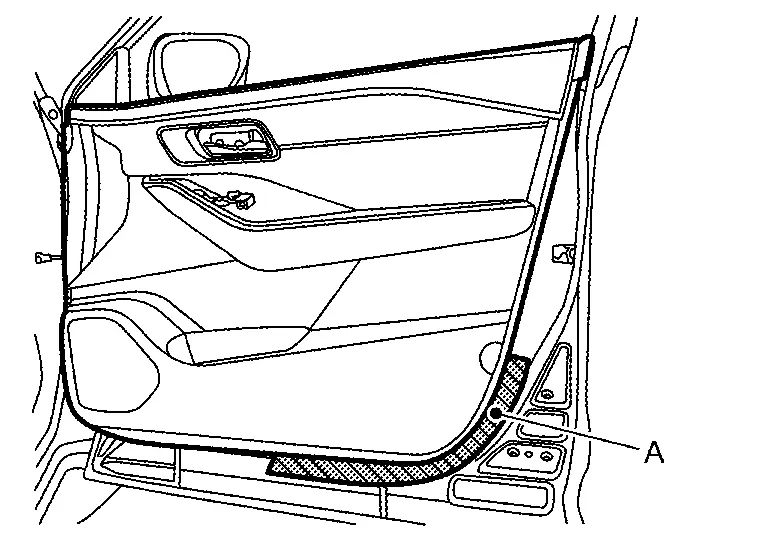
Remove front door finisher mounting screws (A) and mounting bolt (B).
Apply protective tape (A) on front door panel to protect it from damage.
Disengage front door finisher fixing clips using a remover tool (A) according to numerical order 1→2 indicated by arrows as shown in the figure.
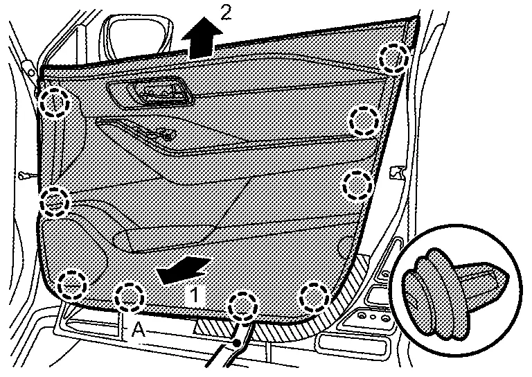
|
: Clip |
Disconnect lock knob cable (1) and inside handle cable (2) from inside handle according to numerical order 1→4 indicated by arrows as shown in the figure, and then remove front door finisher.
Apply protective tapes (A) on front door panel to protect it from damage.
Disengage door corner cover fixing clips using a remover tool (A), and then remove door corner cover.
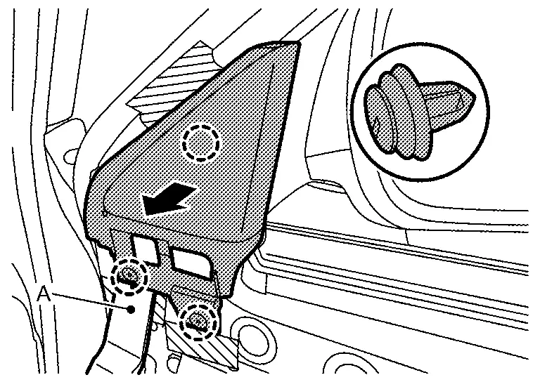
|
: Clip |
Disengage front door weather-strip (1), and then remove inside seal (2) according to numerical order 1→2 indicated by arrows as shown in the figure.
INSTALLATION
Note the following items, and then install in the reverse order of removal.
CAUTION:
-
Visually check clips for deformation and damage during installation. Replace with new ones if necessary.
-
Check in advance that clips are accurately aligned with the portions on front door panel, and then install by pressing in.
-
Never install lock knob cable while it is twisted.
Other materials:
Mac Key Writing
Description
When replacing around view monitor control unit, it is necessary to
write MAC key to around view monitor control unit. Write MAC key to
around view monitor control unit according to "MAC Key writing"
procedure of "CONSULT Operation Manual". Refer to Work Procedure.CAUTION:
During ...
Symptom Diagnosis. Id Registration Cannot Be Completed
Description
The ID of the tire pressure sensor installed in each wheel cannot be
registered in the tire pressure monitoring system. Inspect the tire
pressure sensor or the tire pressure monitoring system circuit.
Diagnosis Procedure
NOTE:
The Signal Tech II Tool [– (NI-50190)] can be used ...
P0461 Fuel Level Sensor
DTC Description
DTC DETECTION LOGICDriving long distances naturally affect fuel gauge level.This diagnosis detects the fuel gauge malfunction of the gauge not moving even after a long distance has been driven. DTC
CONSULT screen terms
(Trouble diagnosis content)
DTC detection condition
...