Nissan Rogue (T33) 2021-Present Owner’s Manual & User Guide: Rear-facing child restraint installation using LATCH
For additional information, refer to all Warnings and Cautions in the “Child safety” and “Child restraints” sections before installing a child restraint.
Do not use the lower anchors if the combined weight of the child and the child restraint exceeds 65 lbs (29.5 kg). If the combined weight is greater than 65 lbs (29.5 kg), use the vehicle seat belt (not the lower anchors) to install the child restraint. Always follow the child restraint manufacturer’s installation instructions.
Follow these steps to install a rear-facing child restraint using the LATCH system in the Nissan Rogue:
1. Position the child restraint on the seat.
Always follow the child restraint manufacturer’s instructions.
Rear-facing web-mounted - step 2
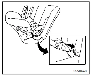
2. Secure the child restraint anchor attachments to the LATCH lower anchors. Check to make sure each LATCH attachment is fully and correctly engaged with the lower anchors.
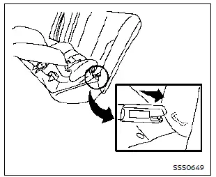
Rear-facing rigid-mounted - step 2
Rear-facing - step 3
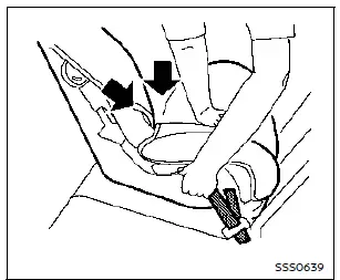
3. For child restraints equipped with webbing-mounted attachments, remove any excess slack from the anchor attachments. Press firmly downward and rearward in the center of the child restraint to compress the Nissan Rogue seat cushion and seatback while tightening the webbing of the anchor attachments.
Rear-facing - step 4
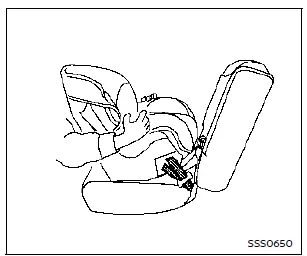
4. After attaching the child restraint, test the installation before placing the child in it. Hold the restraint near the LATCH attachment path and push it from side to side. It should not move more than 1 in (25 mm) side to side. Pull it forward to ensure the LATCH attachments hold it firmly. If the restraint is not secure, tighten the LATCH attachments further, or move the restraint to another seating position and test again. You may need to try a different child restraint or install it using the vehicle seat belt (if allowed by the manufacturer).
Not all child restraints fit all vehicles.
5. Before each use, check that the child restraint remains secure. If it is loose, repeat steps 1 through 4.
Other materials:
Component Parts
Chassis Control System
Without Propilot Assist 2.1
Component Parts Location
A.
View with instrument panel assembly removed
No. Component parts Function
1.
BCM (Body Control Module)
BCM transmits the drive mode select switch to the chassis control module via CAN co ...
Body Construction
Body Construction
Outer side body
Outer front pillar reinforcement
Outer side roof stiffener
Upper inner front pillar
Side dash reinforcement
Upper front pillar bulkhead
Lower front pillar hinge brace
Side cowl top
Upper dash
Hoodledge reinforce ...
Vehicle Security System
System Description
SYSTEM DIAGRAM Component Function
Door switch
Door switch detects door open/close condition and then transmits door switch signal to BCM.
IPDM E/R
IPDM E/R operates horns with horn request signal received from BCM.
IPDM E/R operates headlamps with high be ...