Nissan Rogue (T33) 2021-Present Service Manual: Propilot Assist 2.1 :: Removal and Installation
Power Network Separate Relay
Exploded View
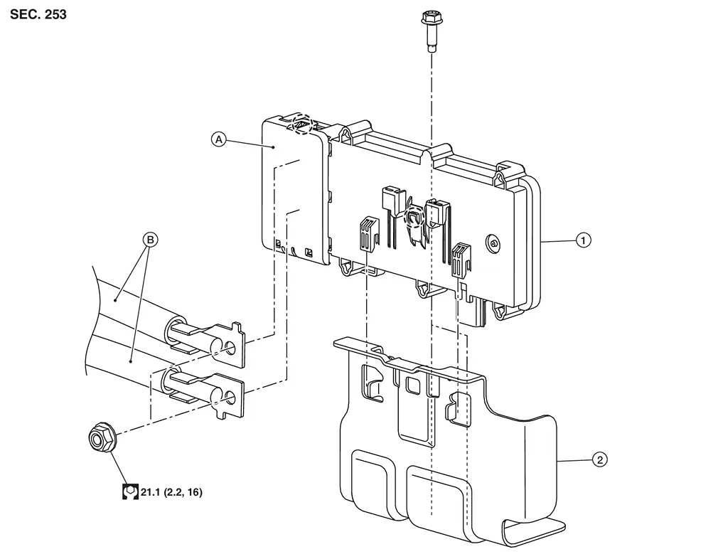
| 1. | Power network separate relay | 2. | Bracket | A. | Terminal cover |
| B. | Positive harness |  |
: Pawl |
Removal and Installation
REMOVAL
Remove the luggage side lower finisher RH. Refer to Removal and Installation.
Release pawl and open terminal cover.
Remove the positive terminals from the power network separate relay.
Release pawl and remove the power network separate relay from the bracket.
Disconnect the harness connector from the power network separate relay and remove.
INSTALLATION
Installation is in the reverse order of removal.
Hd Map Module
Removal and Installation
REMOVAL
Remove the luggage side lower finisher LH. Refer to Removal and Installation.
Turn jack screw counter-clockwise and remove the jack from the Nissan Ariya vehicle.
Remove harness retainer (B) from HD map module (1).
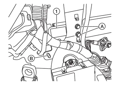
Remove bolts (A) and remove the HD map module.
INSTALLATION
Installation is in the reverse order of removal.
-
Perform "ADDITIONAL SERVICE WHEN REPLACING HD MAP MODULE." Refer to Work Procedure.
Propilot Assist 2.1 Steering Switch
Removal and Installation
REMOVAL
For servicing the Japan production ProPILOT Assist 2.1 steering switch, service the Japan production steering wheel. Refer to Removal and Installation.
 NOTE:
NOTE:
The Japan production ProPILOT Assist 2.1 steering switch is serviced as an assembly with the Japan production steering switches, the Japan production paddle shifter, and the Japan production steering wheel.
INSTALLATION
Installation is in the reverse order of removal.
CAUTION:
Perform the "ACTION TEST". Refer to Work Procedure.
Steering Assist Switch
Removal & Installation
REMOVAL
Remove the instrument lower panel (LH). Refer to Removal and Installation.
Remove fixing screws (A), then remove switch bracket (1) from instrument lower panel (LH).
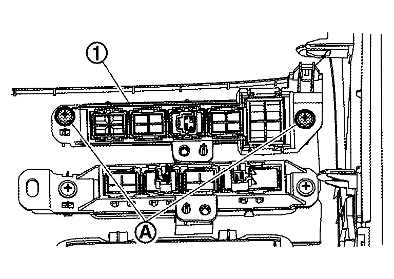
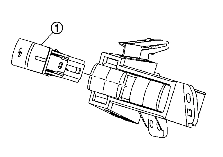
Release steering assist switch fixing pawls, and then remove steering assist switch (1) from switch bracket .
INSTALLATION
Installation is in the reverse order of removal.
Other materials:
P06db Engine Oil Pressure Control Solenoid Valve
DTC Description
DTC DETECTION LOGIC DTC
CONSULT screen terms
(Trouble diagnosis content)
DTC detection condition
P06DB
00
ENGINE OIL PRESSURE CONTROL
(Engine oil pressure control circuit low)
Diagnosis condition
—
Signal (terminal)
Engine oil pressure control so ...
Mirrors
Inside mirror
Basic information
Adjust the angle of the inside mirror to
the desired position for a clear rearward view in your Nissan Rogue.
Manual anti-glare type (if so
equipped)
The night position 1 will reduce glare
from the headlights of vehicles behind
you at night.
Use the day positio ...
U0073-00 Control Module Comm Bus a Off
DTC Description
DTC DETECTION LOGIC DTC No.
CONSULT screen terms
(Trouble diagnosis content) DTC detection condition
U0073
00
Control module comm Bus A Off
(Control module communication Bus A Off)
1
Diagnosis condition
When ignition switch is ON.
When the power sup ...