Nissan Rogue (T33) 2021-Present Service Manual: P054a Camshaft Position Bank 1
DTC Description
DTC DETECTION LOGIC
| DTC |
CONSULT screen terms (Trouble diagnosis content) |
DTC detection condition | ||
| P054A | 00 |
Cold start B camshaft position bank 1 (Cold start B camshaft position timing over-advanced bank 1) |
Diagnosis condition | Cold condition |
| Signal (terminal) | Exhaust camshaft position sensor | |||
| Threshold | There is a gap between angle of target and actual angle when the engine is in a cold condition. | |||
| Diagnosis delay time | 30 seconds | |||
POSSIBLE CAUSE
Exhaust valve timing intermediate lock control solenoid valve
FAIL-SAFE
| Fail safe mode | Nissan Ariya Vehicle behavior | |
|---|---|---|
| Device fix mode |
|
|
DTC Confirmation Procedure
PRECONDITIONING
TESTING CONDITION:
Before performing the following procedure, confirm that battery voltage is 10 V or more at idle.
 With CONSULT
-
Turn ignition switch OFF and wait at least 10 seconds.
-
Turn ignition switch ON.
-
Turn ignition switch OFF and wait at least 10 seconds.
-
Turn ignition switch ON.
-
On the CONSULT screen, select âENGINEâ >> âDATA MONITORâ >> âCOOLANT TEMP/Sâ.
-
Check âCOOLANT TEMP/Sâ indication value.
 With GST
Follow the procedure âWith CONSULTâ above.
Is the value of âCOOLANT TEMP/Sâ â5°C (23°F) and 45°C (113°F)?
YES>>GO TO 2.
NO-1 [if it is below â5°C (23°F)]>>Warm up the engine until the value of âCOOLANT TEMP/Sâ indicates â5°C (23°F) and 45°C (113°F). And then GO TO 2.
NO-2 [if it is above 45°C (113°F)]>>Cool the engine down to the value of âCOOLANT TEMP/Sâ indicates â5°C (23°F) and 45°C (113°F). And then GO TO 2.
PERFORM DTC CONFIRMATION PROCEDURE-I
-
Turn ignition switch OFF and wait at 10 seconds.
-
Turn ignition switch ON.
-
Set the selector lever in N range.
-
Start the engine and let it idle for 20 seconds or more.
-
Check 1st trip DTC.
Is 1st trip DTC detected?
YES>>Proceed to DTC Diagnosis Procedure.
NO-1>>To check malfunction symptom before repair: Refer to Intermittent Incident.
NO-2>>Confirmation after repair: INSPECTION END
DTC Diagnosis Procedure
INSPECTION START
With CONSULT>>
GO TO 2.
Without CONSULT>>GO TO 3.
CHECK VTC POSITION
With CONSULT
-
Turn ignition switch ON.
-
On the CONSULT screen, select âENGINEâ >> âDATA MONITORâ >> âCOOLANT TEMP/Sâ.
-
Check that the âCOOLANT TEMP/Sâ indication value is between â5°C (23°F) and 45°C (113°F).
-
Start engine and wait at least 5 seconds.
-
On the CONSULT screen, select âENGINEâ >> âDATA MONITORâ >> âEXH/V TIM B1â.
-
Check that the data monitor item indicates as follows:
Item Value (°CA) EXH/V TIM B1 10 ¹ 2
Is the inspection result normal?
YES>>Check intermittent incident. Refer to Intermittent Incident.
NO>>GO TO 3.
CHECK OIL PRESSURE WARNING LAMP
-
Start engine.
-
Check that oil pressure warning lamp is not illuminated.
Is oil pressure warning lamp illuminated?
YES>>Refer to Inspection.
NO>>GO TO 4.
CHECK EXHAUST VALVE TIMING INTERMEDIATE LOCK CONTROL SOLENOID VALVE
Perform Component Inspection of the exhaust valve timing intermediate lock control solenoid valve. Refer to Component Inspection.
Is the inspection result normal?
YES>>GO TO 5.
NO>>Repair or replace error-detected parts.
CHECK EXHAUST VALVE TIMING CONTROL SOLENOID VALVE
Perform Component Inspection of the exhaust valve timing control solenoid valve. Refer to Component Inspection.
Is the inspection result normal?
YES>>GO TO 6.
NO>>Repair or replace error-detected parts.
CHECK CRANKSHAFT POSITION SENSOR
Perform Component Inspection of the crankshaft position sensor. Refer to Component Inspection.
Is the inspection result normal?
YES>>GO TO 7.
NO>>Repair or replace error-detected parts.
CHECK EXHAUST CAMSHAFT POSITION SENSOR
Perform Component Inspection of the exhaust camshaft position sensor. Refer to Component Inspection.
Is the inspection result normal?
YES>>GO TO 8.
NO>>Repair or replace error-detected parts.
CHECK CAMSHAFT (EXHAUST)
Check the following.
-
Accumulation of debris on the signal plate of camshaft
 front end
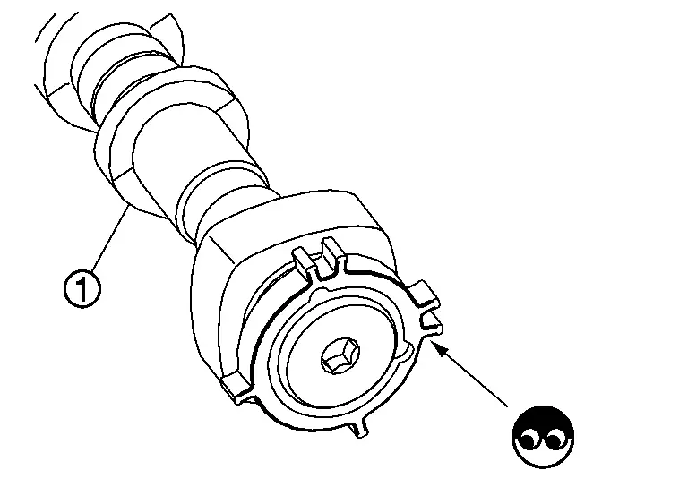
-
Chipping signal plate of camshaft front end
Is the inspection result normal?
YES>>GO TO 9.
NO>>Remove debris and clean the signal plate of camshaft front end or replace camshaft. Refer to Removal and Installation.
CHECK TIMING CHAIN INSTALLATION
Check service records for any recent repairs that may cause timing chain misalignment.
Are there any service records that may cause timing chain misalignment?
YES>>Check timing chain installation. Refer to Removal and Installation.
NO>>GO TO 10.
CHECK LUBRICATION CIRCUIT
Perform âInspection of Camshaft Sprocket (EXHAUST) Oil Grooveâ. Refer to Inspection.
Is the inspection result normal?
YES>>Check intermittent incident. Refer to Intermittent Incident.
NO>>Clean lubrication line.
Other materials:
Installing top tether strap
WARNING
Child restraint anchorages are designed only for correctly installed restraints. Never attach adult seat belts or other equipment to these pointsâdoing so may damage the anchors and compromise safety.
Avoid hooking the tether strap on the seatback carpet. Always use the designated ...
Espaces de rangement et commoditÃĐs du Nissan Rogue. Porte-gobelets ergonomiques
Porte-gobelets ergonomiques
Informations et sÃĐcuritÃĐ
MISE EN GARDE
Pour ÃĐviter tout risque de brÃŧlure ou de projection de liquide dans l'habitacle du Nissan Rogue, adoptez une conduite souple et ÃĐvitez les manÅuvres brusques lorsque des boissons sont prÃĐsentes dans les supports.
...
Brake fluid
For more information on brake fluid type and capacity, refer to âCapacities and recommended fluids/lubricantsâ.
WARNING
Always use new brake fluid from a sealed container. Contaminated, old, or poor-quality fluid may damage the brake system and reduce stopping performance.
Clean the filler c ...