Nissan Rogue (T33) 2021-Present Service Manual: Manifold Absolute Pressure (map) Sensor
Component Inspection
CHECK MANIFOLD ABSOLUTE PRESSURE (MAP) SENSOR
-
Turn ignition switch OFF.
-
Remove manifold absolute pressure (MAP) sensor with its harness connector.
-
Install pressure pump (A) to manifold absolute pressure (MAP) sensor.
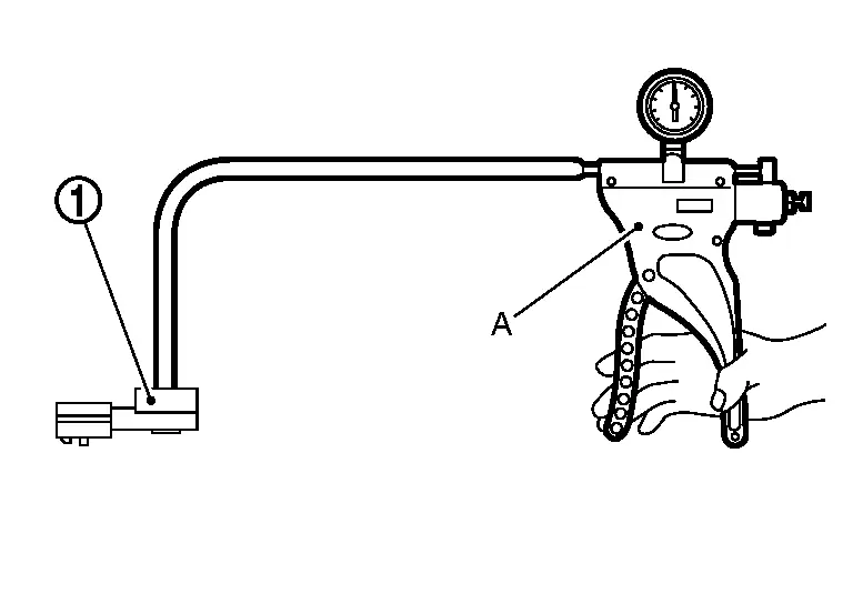
CAUTION:
When insert a pressure pump hose to the sensor, be careful to the damage of the sensor housing.
-
Turn ignition switch ON.
-
Check the voltage between ECM harness connector terminals as follows.
ECM Connector Terminal F71 120 106  NOTE:
NOTE:
’╝┤he sensor is absolute pressure sensor, output value may differ depending on atmospheric pressure and altitude.
-
Measure the atmospheric pressure.
NOTE:
As the atmospheric pressure described on the synoptic chart is the value at sea level, compensate the pressure with the following chart.
Altitude (m) Compensated pressure (hPa) 0 0 200 ŌłÆ24 400 ŌłÆ47 600 ŌłÆ70 800 ŌłÆ92 1000 ŌłÆ114 1500 ŌłÆ168 2000 ŌłÆ218 -
Check the absolute pressure sensor value corresponding to the atmospheric pressure.
Atmospheric pressure (hPa) Voltage (V) 800 1.2 ŌĆō 1.5 850 1.3 ŌĆō 1.5 900 1.3 ŌĆō 1.6 950 1.4 ŌĆō 1.6 1000 1.4 ŌĆō 1.7 1050 1.5 ŌĆō 1.8 -
Confirm the difference of the absolute pressure sensor voltage between at atmospheric pressure condition and at the following vacuumed condition.
NOTE:
-
Always calibrate the pressure pump gauge when using it.
-
Inspection should be done at room temperature [10 - 30┬░C (50 - 86┬░F)].
Condition [Pressure (Relative to atmospheric pressure)] Voltage difference
(Approx.)40 kPa (ŌłÆ300 mmHg) ŌłÆ 0.5 V -
Is the inspection result normal?
YES>>INSPECTION END
NO>>Replace MAP sensor. Refer to Removal and Installation.
Other materials:
Commande de feux de d├®tresse
Appuyez sur cette commande pour signaler aux autres usagers que vous devez vous arr├¬ter ou stationner en urgence. Tous les clignotants du Nissan Rogue fonctionnent alors simultan├®ment.
AVERTISSEMENT
En cas dŌĆÖarr├¬t dŌĆÖurgence, garez le v├®hicule le plus loin possible de la circulatio ...
P2271 Ho2s2
DTC Description
The heated oxygen sensor 2 has a much longer switching time between
rich and lean than the air fuel ratio (A/F) sensor 1. The oxygen storage
capacity of the three way catalyst (manifold) causes the longer
switching time.
: 0.71 V
To judge the malfunctions of heated oxyge ...
Removal and Installation. Rear Door
Exploded View
Rear door panel
Grommet
Rear door striker
TORX bolt
Rear door check link
Rear door hinge (lower)
Rear door hinge (upper)
Rear door weather-strip
Double-sided tape [t: 1.2 mm (0.047 in)]
Double-sided tape [t: 0.8 mm (0.031 in)]
&n ...