Nissan Rogue (T33) 2021-Present Service Manual: Low Pressure Fuel Pump
Component Function Check
CHECK LOW PRESSURE FUEL PUMP FUNCTION
-
Turn ignition switch ON.
-
Pinch fuel feed hose
 with two fingers.
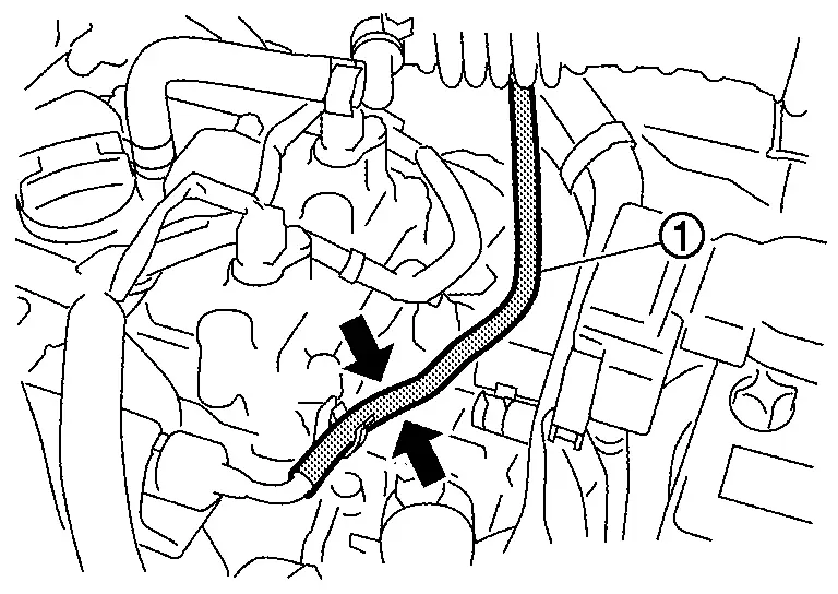
Fuel pressure pulsation should be felt on the fuel feed hose for 1 second after ignition switch is turned ON.
Is the inspection result normal?
YES>>INSPECTION END
NO>>Refer to Diagnosis Procedure.
Diagnosis Procedure
CHECK FUEL PUMP CONTROL MODULE POWER SUPPLY
-
Turn ignition switch OFF.
-
Disconnect Fuel pump control module harness connector.
-
Turn ignition switch ON.
-
Check the voltage between Fuel pump control module harness connector and ground.
+ ŌłÆ Voltage Fuel pump control module Connector Terminal B97 6 Ground Battery voltage
Is the inspection result normal?
YES>>GO TO 5.
NO>>GO TO 2.
CHECK FUEL PUMP CONTROL MODULE POWER SUPPLY CIRCUIT
-
Turn ignition switch OFF.
-
Disconnect IPDM E/R harness connector.
-
Check the continuity between IPDM E/R harness connector and Fuel pump control module harness connector.
IPDM E/R Fuel pump control module Continuity Connector Terminal Connector Terminal E121 46 B97 6 Existed -
Also check harness for short to power and short to ground.
Is the inspection result normal?
YES>>GO TO 3.
NO>>Repair or replace error-detected parts.
CHECK FUSE
-
Pull out 20A fuse (No. 85) from IPDM E/R.
-
Check that 20A fuse is not blowing.
Is the fuse blown (open)?
YES>>Replace the fuse after repairing the applicable circuit.
NO>>GO TO 4.
CHECK INTERMITTENT INCIDENT
Check intermittent incident. Refer to Intermittent Incident.
Is the inspection result normal?
YES>>Perform trouble diagnosis for power supply circuit.
NO>>Repair or replace error-detected parts.
CHECK FUEL PUMP CONTROL MODULE GROUND CIRCUIT
-
Turn ignition switch OFF.
-
Check the continuity between Fuel pump control module harness connector and ground.
Fuel pump control module ŌĆö Continuity Connector Terminal B97 3 Ground Existed -
Also check harness for short to power.
Is the inspection result normal?
YES>>GO TO 6.
NO>>Repair or replace error-detected parts.
CHECK FUEL PUMP CONTROL MODULE INPUT AND OUTPUT CIRCUITS
-
Disconnect ECM harness connector.
-
Check the continuity between Fuel pump control module harness connector and ECM harness connector.
Fuel pump control module ECM Continuity Connector Terminal Connector Terminal B97 4 E21 144 Existed 5 138 -
Also check harness for short to power and short to ground.
Is the inspection result normal?
YES>>GO TO 7.
NO>>Repair or replace error-detected parts.
CHECK FUEL PUMP
Check fuel pump. Refer to Component Inspection.
Is the inspection result normal?
YES>>GO TO 8.
NO>>Replace fuel filter and fuel pump assembly. Refer to Removal and Installation.
CHECK FUEL PUMP CONTROL MODULE
Check fuel pump control module. Refer to Component Inspection.
Is the inspection result normal?
YES>>Check intermittent incident. Refer to Intermittent Incident.
NO>>Replace fuel pump control module. Refer to Removal and Installation.
Other materials:
Dtc/circuit Diagnosis. Rear Window Defogger Switch
Component Function Check
CHECK REAR WINDOW DEFOGGER SWITCH FUNCTION
Check that the indicator lamp of rear window defogger illuminates when rear window defogger switch ON.
Is the inspection result normal?
YES>>
Rear window defogger switch function is OK.
NO>>
Refer to Diagnosis P ...
Component Parts
Automatic Air Conditioning System
Component Parts Location
A.
Instrument panel
B.
Left front of Nissan Ariya vehicle
C.
Right side of blower unit assembly
D.
Right side of heater and cooling unit assembly
E.
Left side of heater and cooling unit assembly
...
Precaution. Precautions
Precaution for Supplemental Restraint System (SRS) "AIR BAG" and "SEAT BELT PRE-TENSIONER"
The Supplemental Restraint System such as ŌĆ£AIR BAGŌĆØ and ŌĆ£SEAT BELT
PRE-TENSIONERŌĆØ, used along with a front seat belt, helps to reduce the
risk or severity of injury to the driver and front passeng ...