Nissan Rogue (T33) 2021-Present Service Manual: Kr15ddt :: Removal and Installation
Radiator
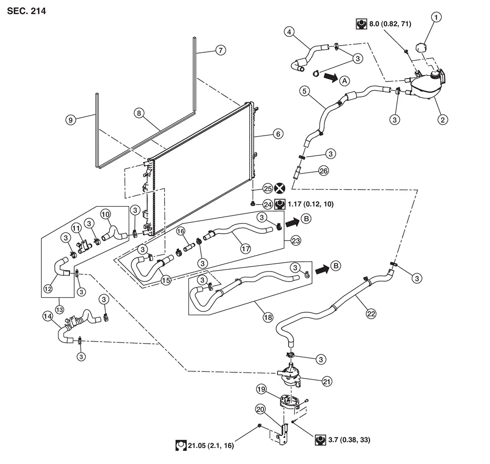
Exploded View
REMOVAL

| 1. | Reservoir tank cap | 2. | Clamp | 3. | Reservoir tank hose |
| 4. | One way valve | 5. | Reservoir tank hose | 6. | Mounting bracket |
| 7. | Clip | 8 | Air guide RH | 9. | Air guide LH |
| 10. | Air guide lower | 11. | Mounting rubber (upper) | 12. | Radiator |
| 13. | Mounting rubber (lower) | 14. | Engine coolant temperature sensor 2 | 15. | O-ring |
| 16. | Radiator drain cock | 17. | Radiator hose [lower (Japan production)] | 18. | Radiator hose [lower (USA production)] |
| 19. | Cooling fan assembly | 20. | Radiator hose (upper) | 21. | Reservoir tank hose |
| 22. | Reservoir tank | A. |
To multi-way control valve. Refer to Exploded View. |
B. |
To water inlet pipe. Refer to Exploded View. |
| C. |
To heater pipe. Refer to Exploded View. |
ŌĆö | ŌĆö | ŌĆö | ŌĆö |
 |
: N┬Ęm (kg-m, in-lb) | ||||
 |
: N┬Ęm (kg-m, in-lb) | ||||
 |
: Always replace after every disassembly. | ||||
Removal and Installation
REMOVAL
WARNING:
-
Never remove reservoir tank cap when engine is hot. Serious burns may occur from high-pressure engine coolant escaping from radiator.
-
Wrap a thick cloth around the reservoir tank cap. Slowly turn it a quarter of a turn to release built-up pressure. Then turn it all the way.
 NOTE:
NOTE:
When removing components such as hoses, tubes/lines, etc., cap or plug openings to prevent fluid from spilling.
Remove engine under cover and engine under cover front. Refer to Removal and Installation.
Remove cooling fan shroud flap if necessary. Refer to Exploded View.
Drain engine coolant from radiator. Refer to Draining.
CAUTION:
-
Perform this step when the engine is cold.
-
Never spill engine coolant on drive belts.
Remove radiator hose (lower) from radiator.
Remove radiator hose (lower) and reservoir tank hose [reservoir tank ŌĆÉ radiator hose (upper)] from engine with the following procedure if necessary:
-
Remove intake manifold. Refer to Removal and Installation.
-
Remove radiator hose (lower) from engine.
-
Remove reservoir tank hose [reservoir tank ŌĆÉ radiator hose (upper)] from engine.
Remove radiator hose (lower) clip from cooling fan shroud.
Remove front grille. Refer to Removal and Installation.
Remove air duct inlet. Refer to Removal and Installation.
Remove air cleaner assembly. Refer to Removal and Installation.
Remove front bumper assembly. Refer to Removal and Installation.
Remove front combination lamp. Refer to Removal and Installation.
Remove radiator core support upper. Refer to Removal and Installation.
Remove mounting bracket.
Remove air guide LH and air guide RH.
Disconnect cooling fan control module harness connector.
Remove cooling fan control module harness clip from cooling fan shroud.
Remove radiator hose (upper) from radiator.
CAUTION:
Never spill engine coolant on drive belt.
Remove radiator hose (upper) from engine with the following procedure if necessary:
CAUTION:
Never spill engine coolant on drive belt.
-
Remove radiator hose (upper) clip from cooling fan shroud.
-
Remove radiator hose (upper) from engine.
Remove sub radiator hose clip from cooling fan shroud.
Remove condenser  from sub radiator
  , and move it frontward.
 |
: Lock |
CAUTION:
-
Be careful not to damage condenser core.
-
Minimize the moving distance of condenser to prevent load to air conditioner piping.
Remove sub radiator from radiator, and move it frontward.
Remove radiator and cooling fan assembly from Nissan Ariya vehicle.

CAUTION:
-
Be careful not to damage radiator core.
-
Minimize the moving distance of condenser to prevent load to air conditioner piping.
Remove cooling fan assembly from radiator.
Remove air guide lower if necessary.
INSTALLATION
Note the following, and install in the reverse order of removal.
CAUTION:
Do not reuse the O-ring.
Radiator hose
CAUTION:
-
Use genuine mounting bolts for the cooling fan assembly and strictly observe the tightening torque. (Breakage prevention for radiator)
NOTE:
-
Insert the radiator hose
all the way to the stopper or by 33 mm (1.30 in) (hose without a stopper).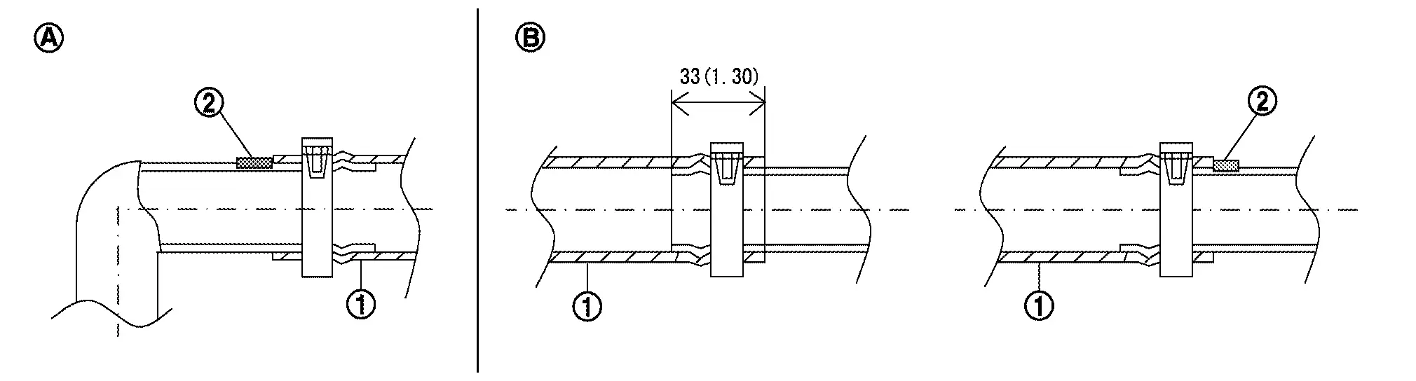
Unit: mm (in) Radiator side 
Engine side -
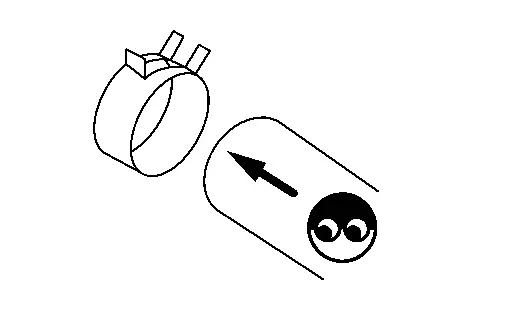
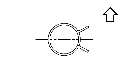
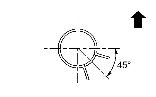
For the orientation of the hose clamp pawl, refer to the figure.
Radiator hose Hose end Paint mark Position of hose clamp*
 ŌĆé: Nissan Ariya Vehicle upper
 Radiator hose (upper) Radiator side Nissan Ariya Vehicle upper 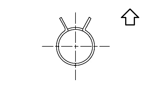
Engine side Lower-right 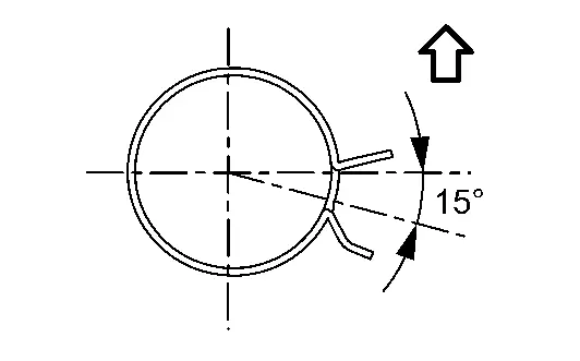
Radiator hose (lower) Radiator side Left 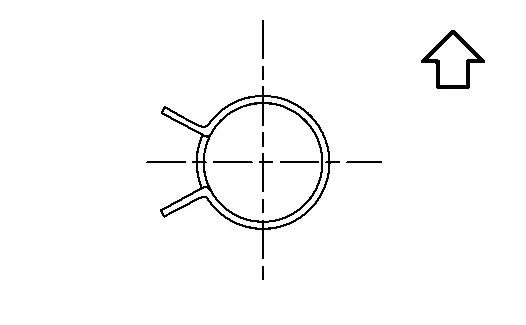
Engine side Left *Refer to the illustrations for the specific position each hose clamp tab.
-
The angle
 created by the hose clamp pawl and the specified line must be within ┬▒30┬░ as shown in the figure.
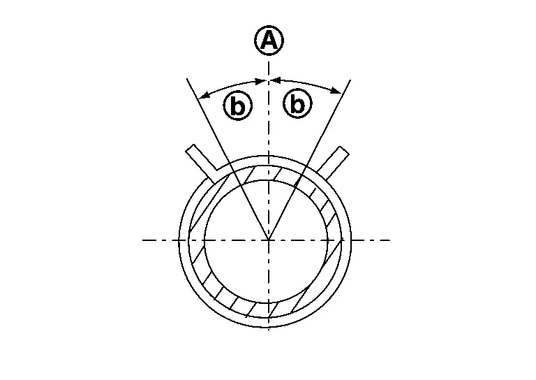
-
To install hose clamps
, check that the dimension (A) from the end of the paint mark to the hose clamp is within the reference value.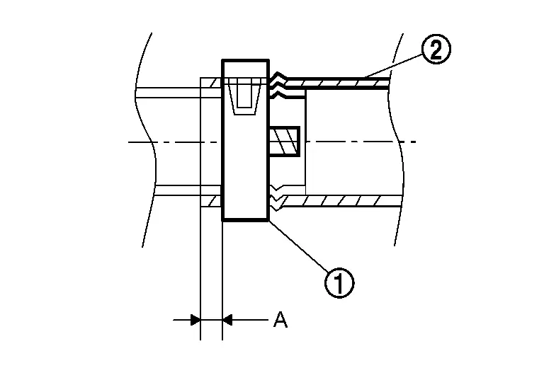
Dimension ŌĆ£AŌĆØ 3 mm - 7 mm (0.12 in - 0.28 in) :Hose
Inspection
INSPECTION AFTER INSTALLATION
-
Check for leakage of engine coolant using the radiator cap tester adapter (commercial service tool) and the radiator cap tester (commercial service tool). Refer to Inspection.
-
Start and warm up the engine. Visually check that there is no leakage of engine coolant.
Sub Radiator
Exploded View
| 1. | Reservoir tank cap | 2. | Reservoir tank | 3. | Clamp |
| 4. | Reservoir tank hose 1 | 5. | Reservoir tank hose 2 | 6. | Sub radiator |
| 7. | Sub radiator side seal RH | 8. | Sub radiator lower seal | 9. | Sub radiator side seal LH |
| 10. | Sub radiator hose (outlet) 1 | 11. | Water hose connector 1 (with water temperature sensor) | 12. | Sub radiator hose (outlet) 2 |
| 13 | Sub radiator hose (outlet) (For NMK production) | 14. | Sub radiator hose (outlet) (For USA production) | 15. | Sub radiator hose (inlet) 1 |
| 16. | Water hose connector 2 | 17. | Sub radiator hose (inlet) 2 | 18. | Sub radiator hose (inlet) (For USA production) |
| 19. | Electric water pump mounting rubber | 20. | Bracket | 21. | Electric water pump |
| 22. | Electric water pump inlet hose | 23. | Sub radiator hose (inlet) (For NMK production) | 24. | Drain plug |
| 25. | O-ring | 26. | Water hose connector 3 | A. | To charge air cooler. Refer to Exploded View. |
| B. | To charge air cooler. Refer to Exploded View. |
Removal & Installation
REMOVAL
Drain air charge cooler coolant from sub radiator. Refer to Draining.
Remove bumper fascia. Refer to Removal and Installation.
Remove air guide LH and air guide RH. Refer to Removal and Installation.
Remove mounting bracket. Refer to Removal and Installation.
Remove condenser from sub radiator, and move it frontward. Refer to Removal and Installation.
Remove sub radiator hose (outlet) 1 and sub radiator hose (inlet) 1 from sub radiator.
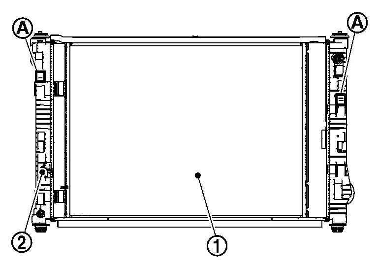
Release tabs (A) on both side of sub radiator (2), then move sub radiator upwards to separate from radiator (1).
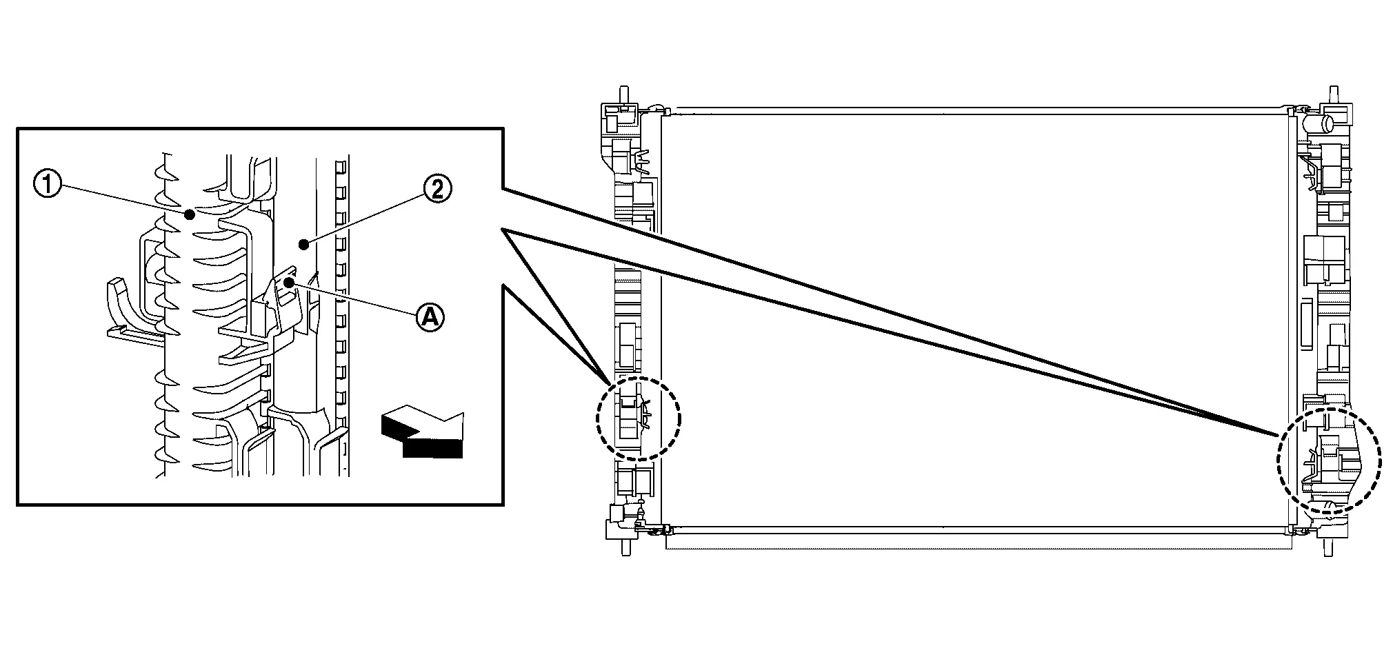
 |
: Nissan Ariya Vehicle front |
CAUTION:
Be careful not to damage radiator core.
INSTALLATION
Note the following, and install in the reverse order of removal.
CAUTION:
Do not reuse the O-ring.
NOTE:
-
This procedure is for charge air cooler system. For procedures involving engine cooling system, refer to Removal and Installation.
-
Water hose marking fit with water pipe marking.
-
Refer to the following table when installing the hose clamps.
| Hose location | Hose end | Direction of paint mark |
Direction of hose clamp tabs
 : Vehicle rear : Vehicle rear |
|---|---|---|---|
| Reservoir tank hose 1 | Reservoir tank side | Nissan Ariya Vehicle upper |
|
| Charge air cooler side | Nissan Ariya Vehicle upper |
|
|
| Reservoir tank hose 2 | Reservoir tank side | Nissan Ariya Vehicle upper |
|
| Water hose connector 3 side | Nissan Ariya Vehicle upper |
|
|
| Sub radiator hose (outlet) 1 | Sub radiator side | Nissan Ariya Vehicle upper |
|
| Water hose connector 2 side | Nissan Ariya Vehicle upper |
|
|
| Sub radiator hose (inlet) 1 | Sub radiator side | Nissan Ariya Vehicle upper |
|
| Water hose connector 1 side | Nissan Ariya Vehicle front |
|
|
| Sub radiator hose (outlet) 2 | Water hose connector 1 side | Nissan Ariya Vehicle front |
|
| Electric water pump side | Nissan Ariya Vehicle upper |
|
|
| Sub radiator hose (inlet) 2 | Water hose connector 2 side | Nissan Ariya Vehicle upper |
|
| Charge air cooler side | Nissan Ariya Vehicle upper |
|
|
| Electric water pump inlet hose | Electric water pump side | Nissan Ariya Vehicle upper |
|
| Water hose connector 3 side | Nissan Ariya Vehicle front |
|
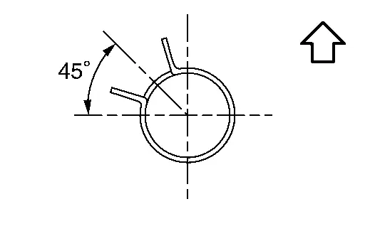
-
The direction of the hose clamp tabs must be within ┬▒30┬░
of the indicated position . -
To install hose clamps
, check that the dimension (A) from the end of the paint mark to the hose clamp is within the reference value.Dimension ŌĆ£AŌĆØ 3 mm - 7 mm (0.12 in - 0.28 in) :Hose
Inspection
INSPECTION AFTER REMOVAL
Check air passages of charge air cooler core and fins for clogging, leaks or deformation. Clean or replace charge air cooler if necessary.
-
Be careful not to deform core fins.
Cooling Fan
Exploded View
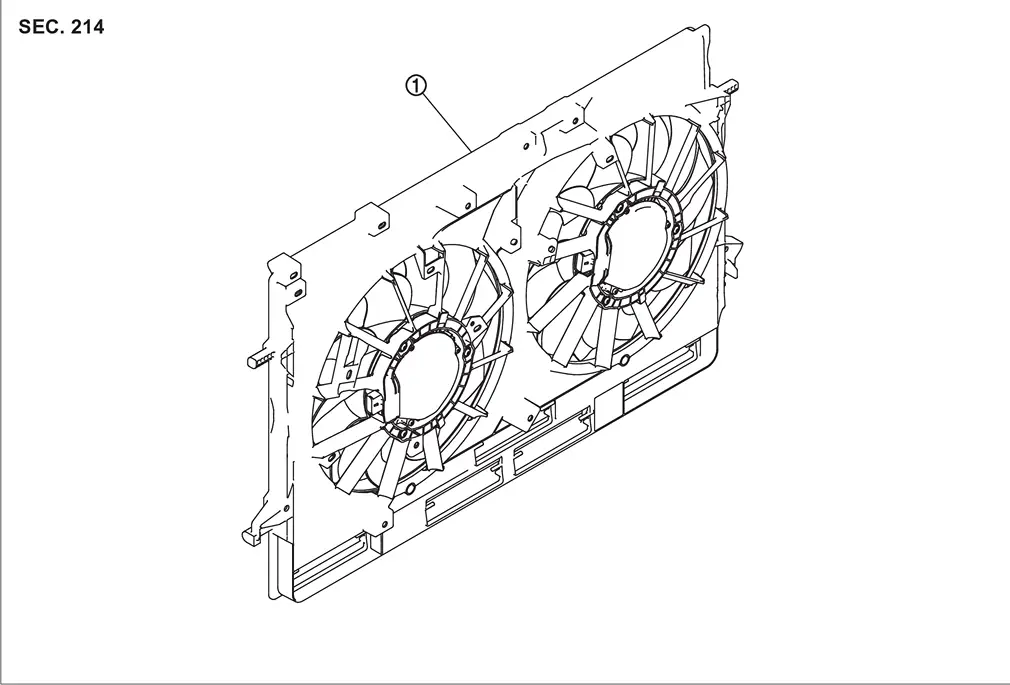
| 1. | Cooling fan assembly | ||||
Removal and Installation
REMOVAL
Remove radiator and cooling fan assembly from vehicle. Refer to Removal and Installation.
CAUTION:
-
Be careful not to damage radiator core.
-
Minimize the moving distance of condenser to prevent load to air conditioner piping.
Remove cooling fan assembly mounting bolts. Refer to Exploded View.
Remove cooling fan assembly from radiator.
Remove cooling fan shroud flap.
INSTALLATION
Note the following, and install in the reverse order of removal.
CAUTION:
Only use genuine parts for fan shroud mounting bolt and observe the specified torque (to prevent radiator from being damaged).
NOTE:
Cooling fans are controlled by ECM. For details. Refer to Cooling Fan.
Inspection
INSPECTION AFTER DISASSEMBLY
Cooling Fan
Inspect cooling fan for crack or unusual bend.
-
If anything is found, replace cooling fan.
Water Pump
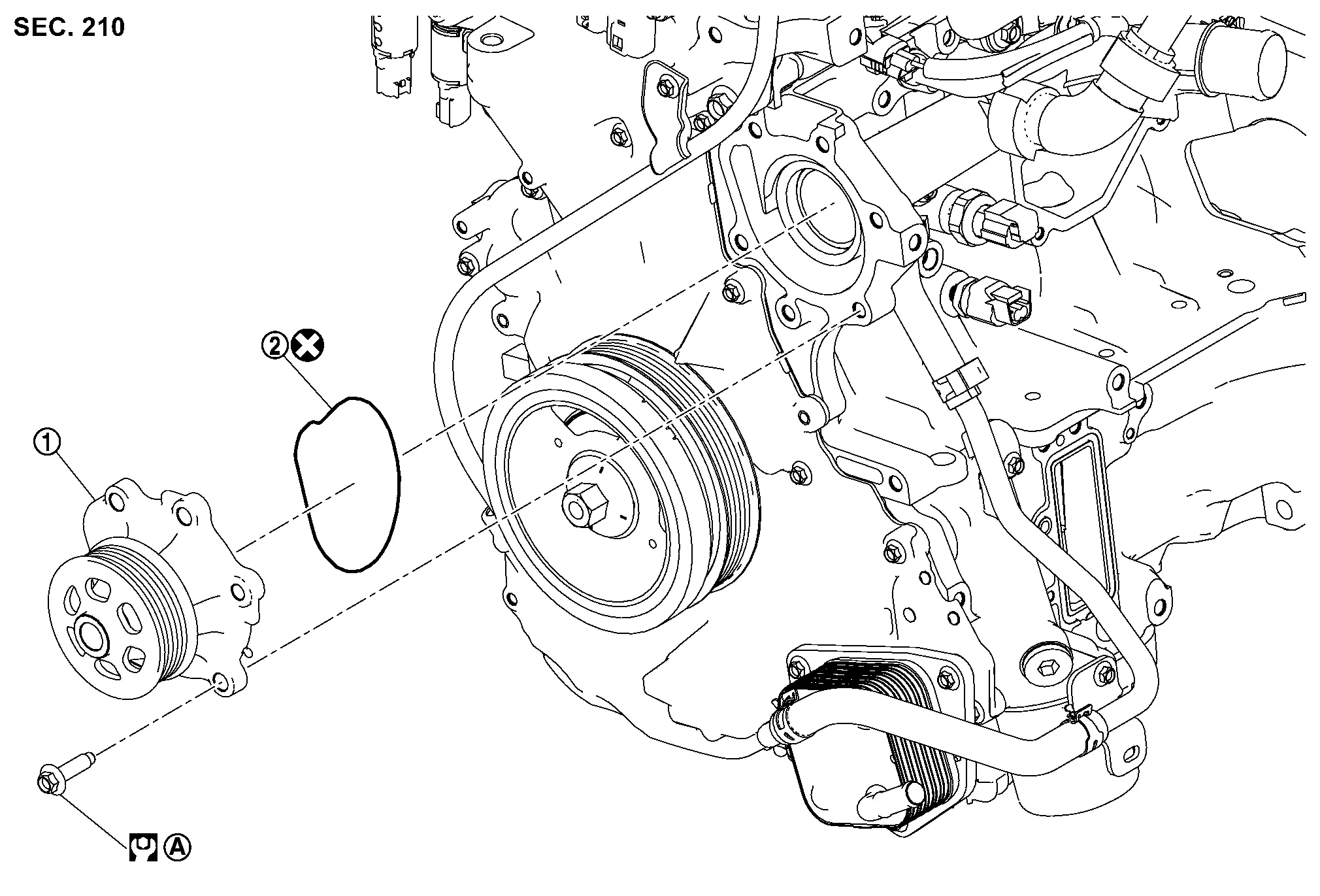
Exploded View
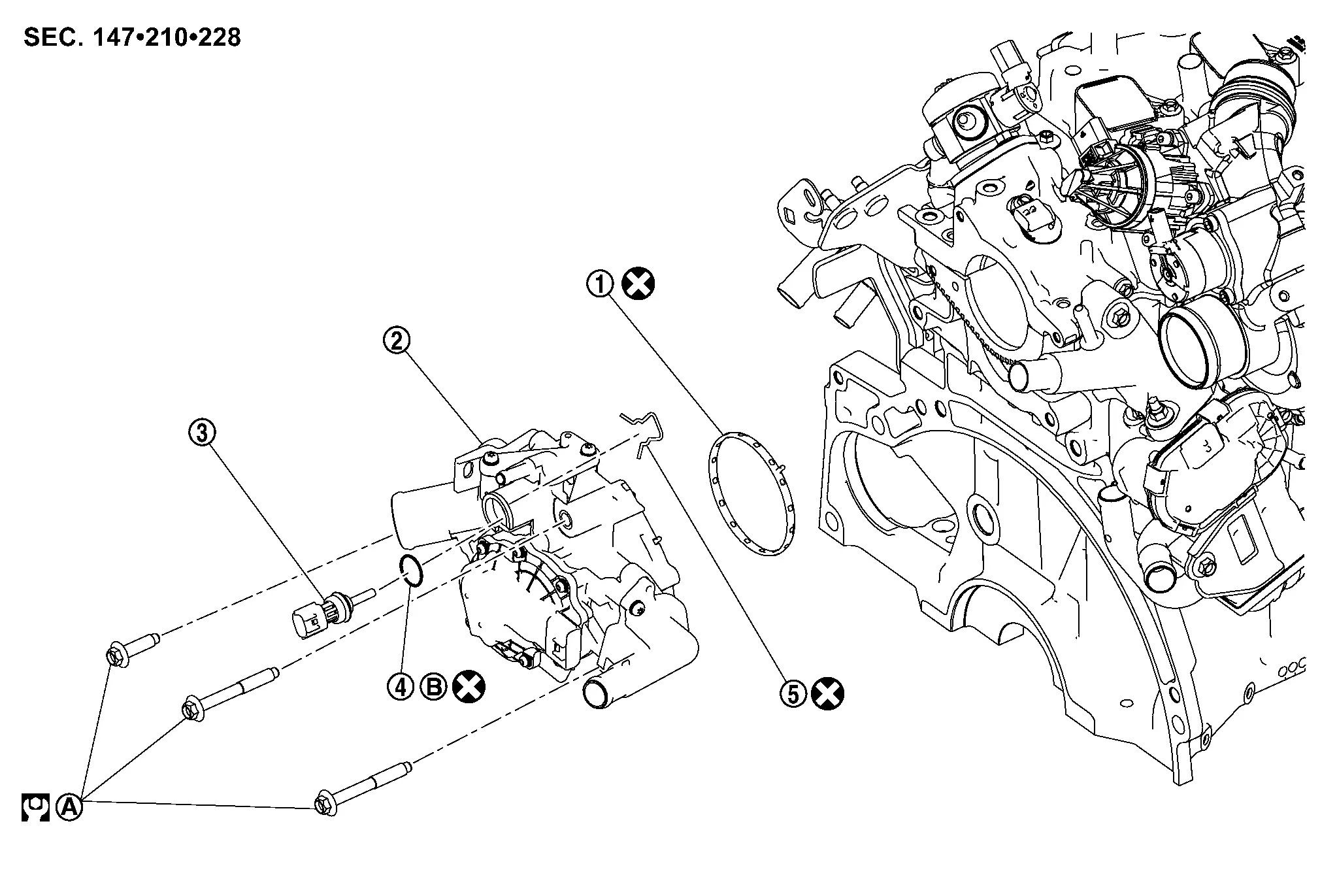
|
Water pump assembly | |
Rubber ring | ||
|
Comply with the assembly procedure when tightening. Refer to Removal and Installation. | ||||
|
: Always replace after every disassembly. | ||||
|
: N┬Ęm (kg-m, ft-lb) | ||||
With Idle Start/stop System
Removal and Installation
REMOVAL
Drain engine coolant from radiator. Refer toDraining.
CAUTION:
Perform this step when the engine is cold.
Remove the wheel and tire (front RH). Refer to Removal & Installation.
Remove the splash guard (front RH). Refer to Exploded View.
Remove the front spoiler. Refer to Removal and Installation.
Remove the fender protector (RH) front side clip and keep a service area. Refer to Removal and Installation.
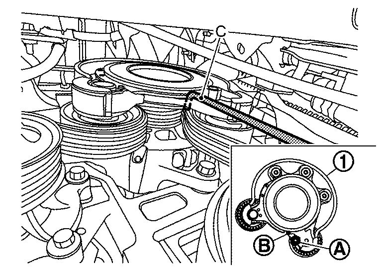
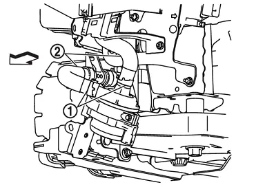
Securely hold the hexagonal part (A) of the drive belt auto-tensioner
(1) with a suitable tool (C), and move it the direction of arrow ( ) (loosening direction of tensioner).
CAUTION:
Avoid placing hand in a location where pinching may occur if the holding tool accidentally comes off.
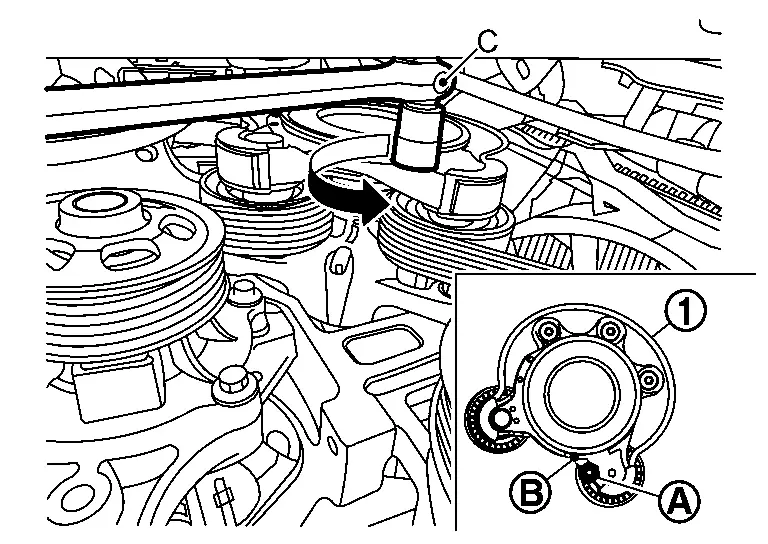
| B. | :Retaining hole |
Turn counterclockwise until the tensioner lock hole.
Insert a rod (C) approximately 4.0 mm (0.157 in.) in diameter through the rear of the drive belt auto-tensioner into retaining hole (B) to lock drive belt auto-tensioner pulley.
NOTE:
Leave drive belt auto-tensioner pulley arm locked until drive belt is installed again.
| (1) | :Drive belt auto-tensioner |
| (A) | :Hexagonal part |
Remove the drive belt from the water pump pulley.
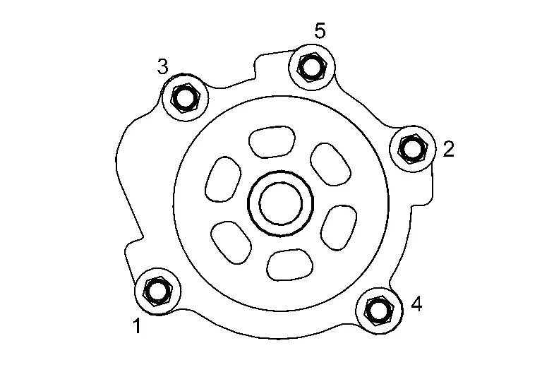
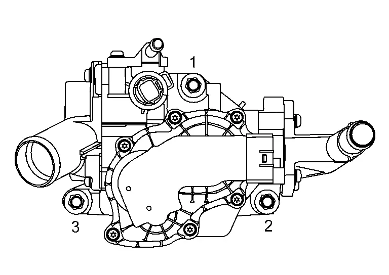
Loosen water pump bolts in reverse of the sequence shown and remove the multi-way control valve.
CAUTION:
Do not reuse rubber ring.
INSTALLATION
Installation is in the reverse order of removal.
CAUTION:
Do not reuse rubber ring.
-
Tighten water pump bolts to the specified torque in the sequence shown.
Bolts :25 N┬Ęm (2.6 kg-m, 18 ft-lb) -
Refill the cooling system. Refer to Refilling.
Inspection
INSPECTION AFTER REMOVAL
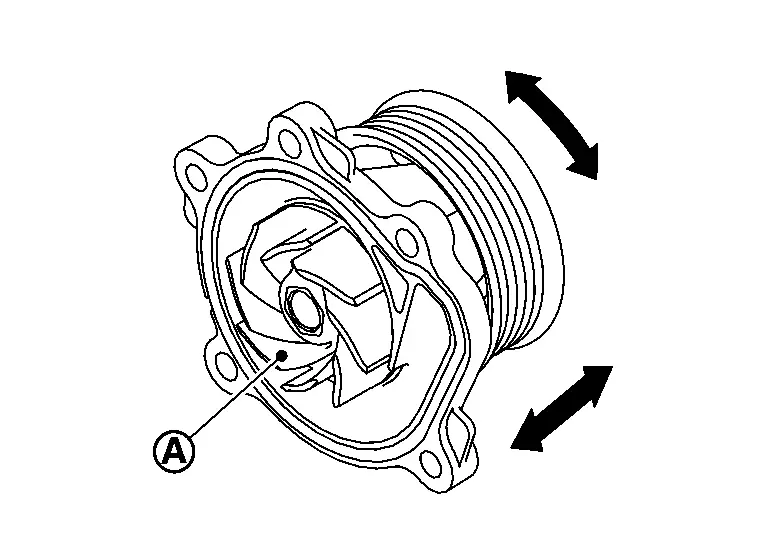
-
Check visually that there is no significant dirt or rusting on water pump body and vane
.
-
Check that there is no looseness in vane shaft, and that it turns smoothly when rotated by hand.
-
Replace water pump, if necessary.
INSPECTION AFTER INSTALLATION
-
Check for leakage of engine coolant using the radiator cap tester adapter (commercial service tool) and the radiator cap tester (commercial service tool). Refer to Inspection.
-
Start and warm up the engine. Check visually that there is no leakage of engine coolant.
Electric Water Pump
Exploded View
| 1. | Reservoir tank cap | 2. | Reservoir tank | 3. | Clamp |
| 4. | Reservoir tank hose 1 | 5. | Reservoir tank hose 2 | 6. | Sub radiator |
| 7. | Sub radiator side seal RH | 8. | Sub radiator lower seal | 9. | Sub radiator side seal LH |
| 10. | Sub radiator hose (outlet) 1 | 11. | Water hose connector 1 (with water temperature sensor) | 12. | Sub radiator hose (outlet) 2 |
| 13 | Sub radiator hose (outlet) (For NMK production) | 14. | Sub radiator hose (outlet) (For USA production) | 15. | Sub radiator hose (inlet) 1 |
| 16. | Water hose connector 2 | 17. | Sub radiator hose (inlet) 2 | 18. | Sub radiator hose (inlet) (For USA production) |
| 19. | Electric water pump mounting rubber | 20. | Bracket | 21. | Electric water pump |
| 22. | Electric water pump inlet hose | 23. | Sub radiator hose (inlet) (For NMK production) | 24. | Drain plug |
| 25. | O-ring | 26. | Water hose connector 3 | A. | To charge air cooler. Refer to Exploded View. |
| B. | To charge air cooler. Refer to Exploded View. |
Removal and Installation
REMOVAL
Drain the engine coolant from the radiator. Refer to Draining.
CAUTION:
Perform this step when the engine is cold.
Remove the wheel and tire (front LH). Refer to Removal & Installation.
Remove the front spoiler (LH). Refer to Removal and Installation.
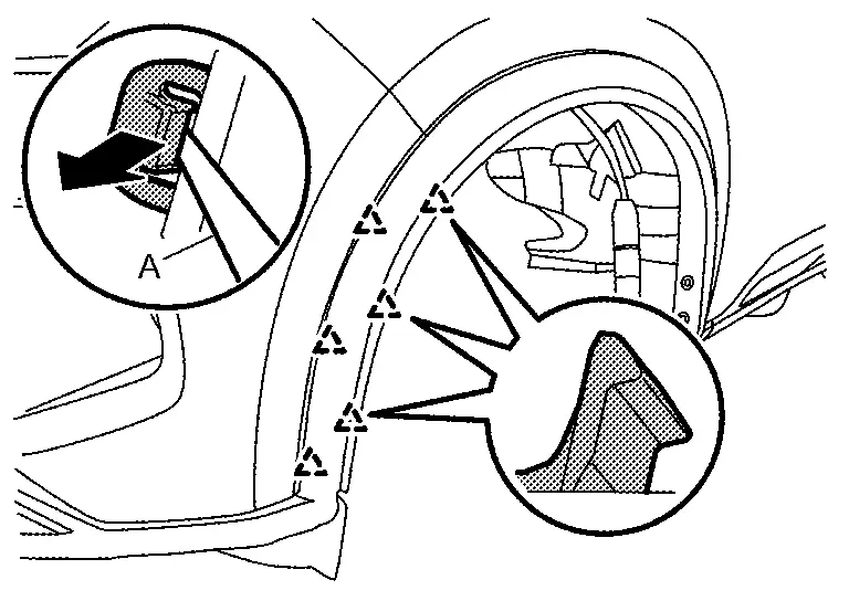
Remove the front fillet molding fixing screws (A).
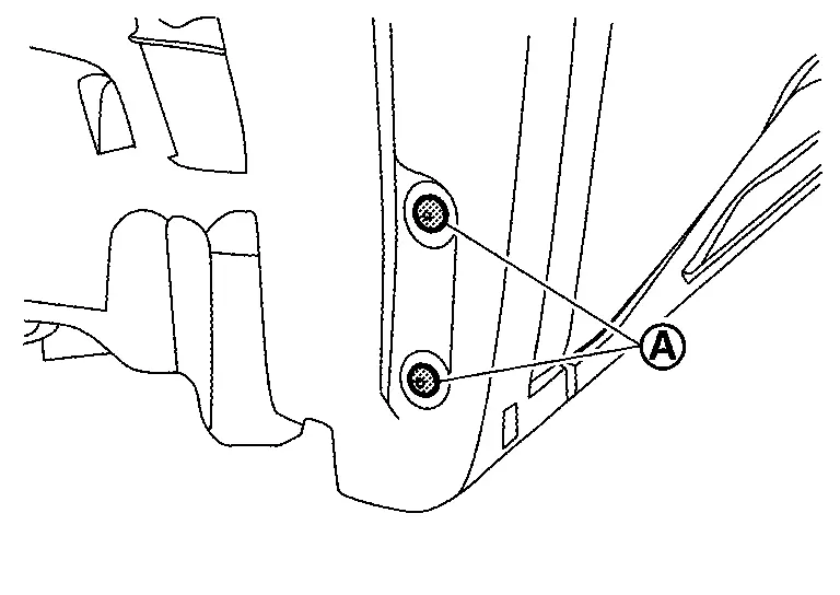
Disengage the front fillet molding fixing pawls using a remover tool (A) as shown by the arrow in the figure.
Remove the engine under cover front and the engine under cover. Refer to Removal and Installation.
Remove the splash guard fixing clips, and then remove the splash guard.
Remove the front fender protector fixing screw (A) and clip (B) of the front fender protector front side (LH).
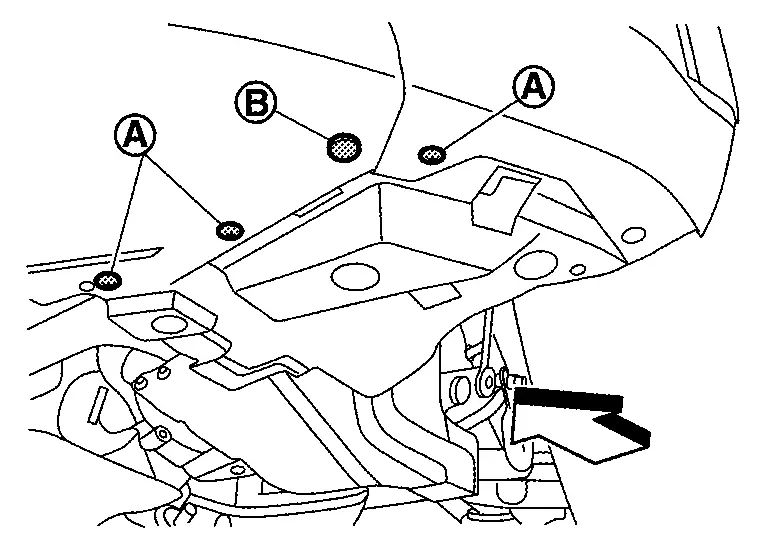
Remove the screw grommet and position the fender protector (LH) aside.
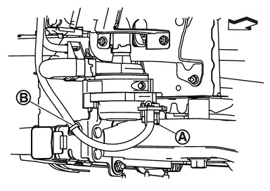
Disconnect the electric water pump harness connector (A) and remove the wire harness push pin (B).
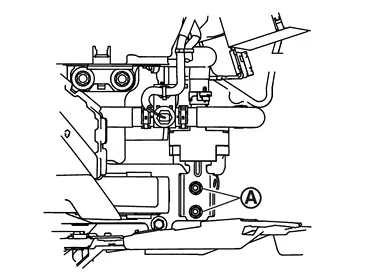
Remove the 2 electric water pump nuts (A) and position aside electric water pump.
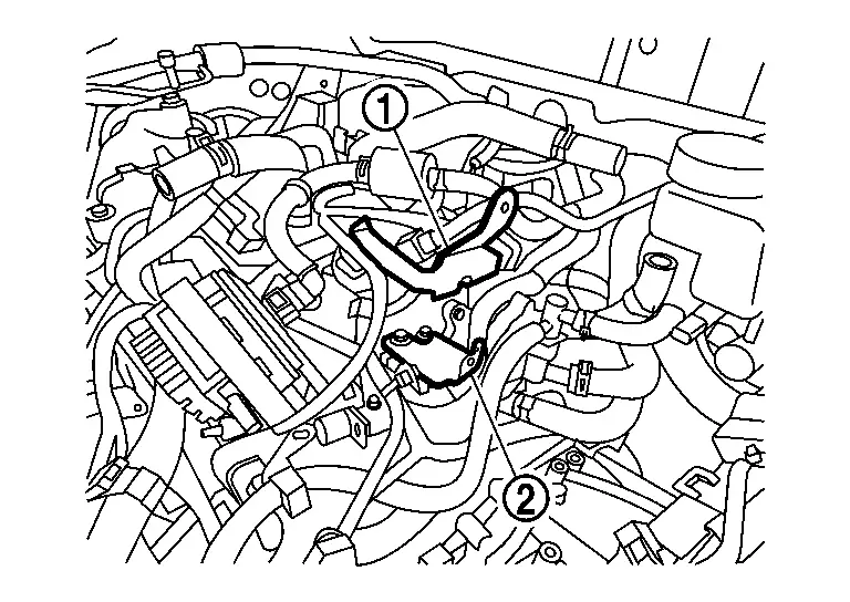
Remove the hose clamps (1), and disconnect the electric water pump hoses (2). Remove the electric water pump.
INSTALLATION
Installation is in the reverse order of removal.
Refill the engine coolant. Refer to Refilling.
Inspection
INSPECTION AFTER INSTALLATION
-
Check for leakage of engine coolant using the radiator cap tester adapter (commercial service tool) and the radiator cap tester (commercial service tool). Refer to Inspection.
-
Start and warm up the engine. Check visually that there is no leakage of engine coolant.
Multi-Way Control Valve
Exploded View
|
Rubber ring | |
Multi-way control valve |  |
Water temperature sensor 1 |
 |
O ring |  |
Clip | ||
|
: Comply with the assembly procedure when tightening. Refer to Removal and Installation. | ||||
|
Apply Genuine NISSAN Long Life Antifreeze/Coolant (blue) or equivalent. | ||||
|
: N┬Ęm (kg-m, ft-lb) | ||||
Removal and Installation
REMOVAL
Drain engine coolant from radiator. Refer to Draining.
CAUTION:
-
Perform this step when engine is cold.
-
Never spill engine coolant on drive belt.
Remove air duct. Refer to Removal and Installation.
Remove air cleaner assembly. Refer to Removal and Installation.
Remove 12V battery. Refer to Removal and Installation.
Disconnect ECM harness connectors from ECM.
Remove battery tray 1. Refer to Removal and Installation.
Disconnect brake fluid level switch harness connector. Refer to Exploded View (WITHOUT ProPILOT ASSIST 2.1) or Exploded View (WITH ProPILOT ASSIST 2.1).
Disconnect engine harness from battery tray 2.
Remove battery tray 2. Refer to Removal and Installation.
Remove air duct and air duct hose. Refer to Removal and Installation.
Disconnect radiator hose (upper) from multi-way control valve. Refer to Removal and Installation.
Remove bracket 1 and air duct bracket .
Remove each water hoses from multi-way control valve.
Disconnect the engine coolant temperature sensor 1 harness connector.
If necessary, remove the engine coolant temperature sensor 1 from the multi-way control valve.
CAUTION:
Do not reuse the O-ring.
Disconnect the harness connector from the multi-way control valve.
Loosen multi-way control valve bolts in reverse of the sequence shown and remove the multi-way control valve.
CAUTION:
Do not reuse rubber ring.
INSTALLATION
Note the following, and install in the reverse order of removal.
CAUTION:
-
Do not reuse rubber ring and O-ring.
-
Do not reuse clip.
-
Care should be taken not to apply scratches, dents and foreign bodies to the respective surfaces for mounting gasket and water temperature sensor 1.
-
Be careful to install the rubber ring in the correct position.
-
Make sure the rubber ring is free from separation and contamination with oil.
-
O-ring should be installed to water temperature sensor 1 without being twisted. After that, apply Genuine NISSAN Long Life Antifreeze/Coolant (blue) to outer peripheral surface of O-ring and install water temperature sensor 1 to multi-way control valve.
-
Attach the clip
from the notch side () when attaching the clip of the water temperature sensor 1.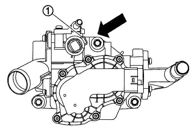
-
Tighten the multi-way control valve bolts to the specified torque in the sequence shown.
Multi-way control valve bolts
: 25 N┬Ęm (2.6 kg-m, 18 ft-lb) -
Refill the engine coolant. Refer to Refilling.
Inspection
-
After installation, check engine coolant systems for leaks. Refer to Inspection.
-
Start and warm up the engine. Check and make sure there are no engine coolant leaks.
Water Piping
Exploded View
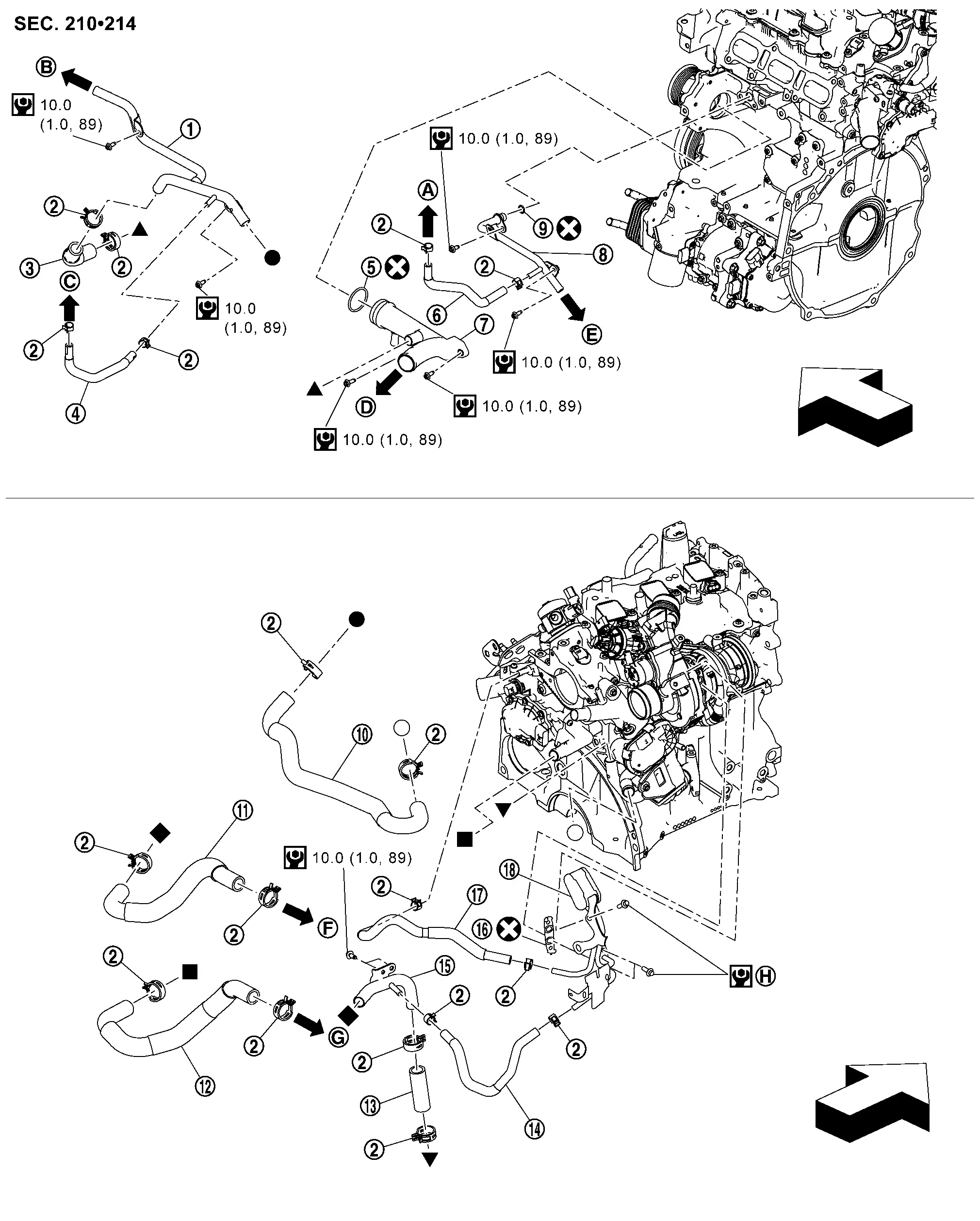
|
Heater pipe | |
Clamp | |
Water hose 1 |
|
Water hose 2 | |
O ring |  |
Water hose 3 |
 |
Water inlet pipe |  |
Water pipe 1 |  |
O ring |
 |
Water hose 4 |  |
Water hose 5 |  |
Water hose 6 |
 |
Water hose 7 |  |
Water hose 8 |  |
Water pipe 2 |
 |
Gasket |  |
Water hose 9 |  |
Water pipe 3 |
|
To electric throttle control actuator. Refer to Exploded View. | |
To reservoir tank. Refer to Exploded View. |  |
To electric throttle control actuator. Refer to Exploded View. |
 |
To Radiator hose (lower). Refer to Exploded View. |  |
To CVT oil warmer. Refer to Exploded View. |  |
To heater and cooling unit assembly. Refer to Exploded View. |
 |
To heater and cooling unit assembly. Refer to Exploded View. |  |
Comply with the assembly procedure when tightening. Refer to Removal and Installation. | ||
| : Engine front | |||||
|
: N┬Ęm (kg-m, in-lb) | ||||
|
: Always replace after every disassembly. | ||||
 , ,  , ,  , ,  , ,  , ,  : Indicates that the part is connected at points with same symbol in actual Nissan Ariya vehicle. : Indicates that the part is connected at points with same symbol in actual Nissan Ariya vehicle. |
|||||
Removal and Installation
REMOVAL
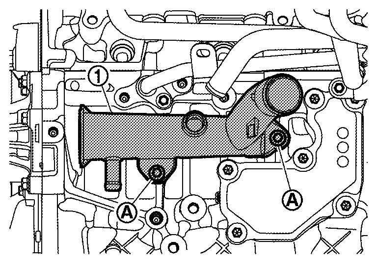
WATER INLET PIPE
Drain engine coolant. Refer to Draining.
CAUTION:
-
Perform this step when engine is cold.
-
Never spill engine coolant on drive belts.
Remove intake manifold. Refer to Removal and Installation.
Remove heater pipe.
Remove the sub starter & generator. Refer to Removal and Installation.
Remove the sub starter & generator and compressor bracket. Refer to Exploded View.
Remove water hose 2.
Remove radiator hose (lower) (water inlet pipe side). Refer to Exploded View.
Remove water hose 5.
Remove harness cramp from water inlet pipe.
Remove water inlet pipe mounting bolts (A), and then remove water inlet pipe (1) from engine.
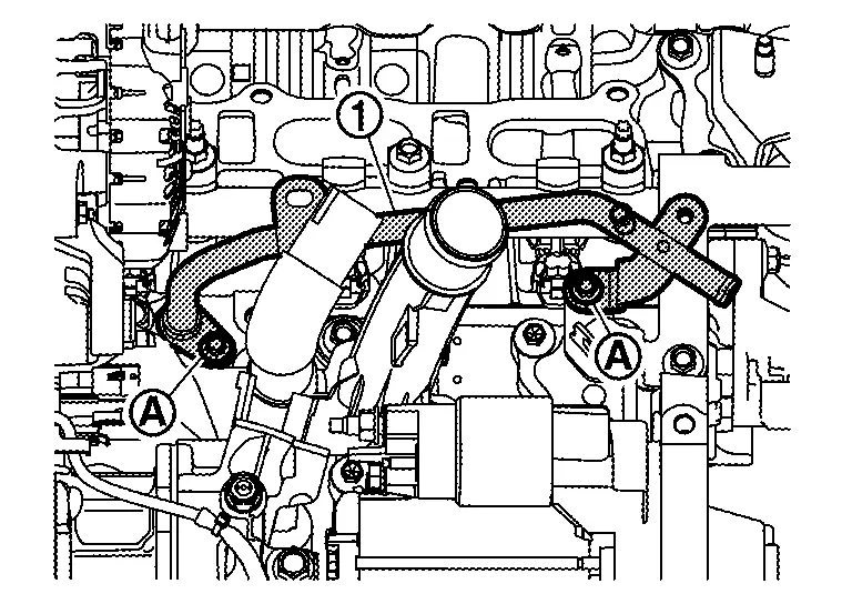
WATER PIPE 2
Drain engine coolant. Refer to Draining.
CAUTION:
-
Perform this step when engine is cold.
-
Never spill engine coolant on drive belts.
Remove intake manifold. Refer to Removal and Installation.
Remove heater pipe.
Remove fuel injector rail insulator. Refer to Removal and Installation.
Disconnect fuel injector harness clip. Refer to Removal and Installation.
Remove water hose 6.
Remove CVT water hose (water pipe 2 side) . Refer to Exploded View.
Remove water pipe 2 mounting bolts (A), and then remove water pipe 2 (1) from engine.
INSTALLATION
Note the following, and install in the reverse order of removal.
Inspection
INSPECTION AFTER INSTALLATION
-
Check for leakage of engine coolant using the radiator cap tester adapter (commercial service tool) and the radiator cap tester (commercial service tool). Refer to Inspection.
-
Start and warm up the engine. Check visually that there is no leakage of engine coolant.
Other materials:
Ecu Diagnosis Information. 12v Sub Battery (lithium Ion Battery)
DTC Index
Self Diagnostic Result DTC Display contents of CONSULT Reference
P1A00-49
Lithium ion battery 12V
DTC Description
P1A01-A2
Lithium ion battery 12V
DTC Description
P1A01-A3
Lithium ion battery 12V
DTC Description
P1A04-97
Lithium ion battery 12V
...
Cold weather driving
Freeing a frozen door lock
To help prevent a frozen door lock, apply deicer through the key hole before freezing occurs. If the lock becomes frozen, gently heat the key before inserting it into the key hole, or use the Intelligent Key system.
Anti-freeze
When outside temperatures are expected to dr ...
Symptom Diagnosis. Squeak and Rattle Trouble Diagnoses
Work Flow
CUSTOMER INTERVIEWInterview
the customer if possible, to determine the conditions that exist when
the noise occurs. Use the Diagnostic Worksheet during the interview to
document the facts and conditions when the noise occurs and any customer
comments. Refer to Diagnostic Worksheet ...