Nissan Rogue (T33) 2021-Present Service Manual: Kr15ddt :: Precaution. Precautions
Precautions
Precaution for Supplemental Restraint System (SRS) "AIR BAG" and "SEAT BELT PRE-TENSIONER"
The Supplemental Restraint System such as “AIR BAG” and “SEAT BELT PRE-TENSIONER”, used along with a front seat belt, helps to reduce the risk or severity of injury to the driver and front passenger for certain types of collisions.
Information necessary to service the system safely is included in the “SRS AIR BAG” and “SEAT BELT” sections of this Service Manual.
WARNING:
Always observe the following items for preventing accidental activation:
-
To avoid rendering the SRS inoperative, which could increase the risk of personal injury or death in the event of a collision that would result in air bag inflation, it is recommended that all maintenance and repair be performed by an authorized NISSAN/INFINITI dealer.
-
Improper repair, including incorrect removal and installation of the SRS, can lead to personal injury caused by unintentional activation of the system. For removal of Spiral Cable and Air Bag Module, see “SRS AIR BAG”.
-
Never use electrical test equipment on any circuit related to the SRS unless instructed to in this Service Manual. SRS wiring harnesses can be identified by yellow and/or orange harnesses or harness connectors.
PRECAUTIONS WHEN USING POWER TOOLS (AIR OR ELECTRIC) AND HAMMERS
WARNING:
Always observe the following items for preventing accidental activation:
-
When working near the Air Bag Diagnosis Sensor Unit or other Air Bag System sensors with the ignition/power switch ON or engine running, never use air or electric power tools or strike near the sensor(s) with a hammer. Heavy vibration could activate the sensor(s) and deploy the air bag(s), possibly causing serious injury.
-
When using air or electric power tools or hammers, always place the ignition/power switch in the OFF position, disconnect the 12V battery or batteries, and wait at least 3 minutes before performing any service.
Precautions for Removing Battery Terminal
-
With the adoption of Auto ACC function, ACC power is automatically supplied by operating the Intelligent Key or remote keyless entry or by opening/closing the driver side door. In addition, ACC power is supplied even after the ignition switch is in the OFF position, i.e. ACC power is supplied for a certain fixed time.
-
When disconnecting the 12V battery terminal, place the ignition switch in the off position before disconnecting the 12V battery terminal, observing “How to disconnect 12V battery terminal” described below.
 NOTE:
NOTE:
Some ECUs operate for a certain fixed time even after ignition switch is in the OFF position and ignition power supply is stopped. If the battery terminal is disconnected before ECU stops, accidental DTC detection or ECU data damage may occur.
-
For Nissan Ariya vehicles with the 2-batteries, be sure to connect the main battery and the sub battery before placing the ignition switch in the ON position.
NOTE:
If the ignition switch is in the ON position with any one of the terminals of main battery and sub battery disconnected, then DTC may be detected.
-
After installing the 12V battery, always check "Self Diagnosis Result" of all ECUs and erase DTC.
NOTE:
The removal of 12V battery may cause a DTC detection error.
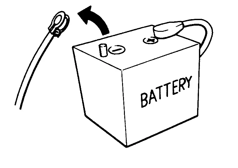
HOW TO DISCONNECT 12V BATTERY TERMINAL
Disconnect 12V battery terminal according to instruction described below.
-
Open the hood.
-
Place the ignition switch in the ON position.
-
Place the ignition switch in the OFF position with the driver side door opened.
-
Get out of the Nissan Ariya vehicle and close the driver side door.
-
Wait at least 3 minutes.
CAUTION:
While waiting, never operate the Nissan Ariya vehicle such as locking, opening, and closing doors. Violation of this caution results in the activation of ACC power supply according to the Auto ACC function.
-
Remove 12V battery terminal.
CAUTION:
After installing 12V battery, always check self-diagnosis results of all ECUs and erase DTC.
General Precautions
WARNING:
When replacing fuel line parts, be sure to observe the following.
-
Put a “CAUTION: FLAMMABLE” sign in the workshop.
-
Be sure to work in a well ventilated area and furnish workshop with a CO2 fire extinguisher.
-
Never smoke while servicing fuel system. Keep open flames and sparks away from the work area.
CAUTION:
-
Use gasoline required by the regulations for octane number. Refer to Fuel.
-
Before removing fuel line parts, perform out the following procedures:
-
Put drained fuel in an explosion-proof container and put the lid on securely. Keep the container in safe area.
-
Release fuel pressure from the fuel lines. Refer to Work Procedure.
-
Disconnect the battery cable from the negative terminal.
-
-
Always replace O-ring and clamps with new ones.
-
Never bend or twist tubes when they are being installed.
-
Never tighten hose clamps excessively to avoid damaging hoses.
-
After installing tubes, check that there is no fuel leakage at connections in the following steps.
-
Apply fuel pressure to fuel lines with turning ignition switch “ON” (with engine stopped). Then check for fuel leakage at connections.
-
Start engine and rev it up and check for fuel leakage at connections.
-
-
Use only a genuine NISSAN fuel filler cap as a replacement. If an incorrect fuel filler cap is used, the “MIL” may come on.
Other materials:
Ipdm E/r. Precaution. Precautions
Precautions
Precaution for Supplemental Restraint System (SRS) "AIR BAG" and "SEAT BELT PRE-TENSIONER"
The Supplemental Restraint System such as “AIR BAG” and “SEAT BELT
PRE-TENSIONER”, used along with a front seat belt, helps to reduce the
risk or severity of injury to the driver and ...
P3194 Icc System
DTC Description
DTC DETECTION LOGIC DTC
CONSULT screen terms
(Trouble diagnosis content)
DTC detection condition
P3194
00
Cruise control communication
(Adaptive Cruise Control CAN wheel speed information unavailable or absent)
Diagnosis condition
Ignition switch ON
S ...
U19b1-87 Can Comm Circuit
DTC Description
CAN COMMUNICATIONCAN (Controller Area Network) is a serial
communication line for real time applications. It is an on-Nissan Ariya
vehicle multiplex communication line with high data communication speed
and excellent error detection ability. Modern Nissan Ariya vehicle is
eq ...