Nissan Rogue (T33) 2021-Present Service Manual: Kr15ddt :: Precaution
Precautions for Supplemental Restraint System (srs) Air Bag and Seat Belt Pre-Tensioner
PRECAUTIONS FOR SUPPLEMENTAL RESTRAINT SYSTEM (SRS) AIR BAG AND SEAT BELT PRE-TENSIONER : Precautions
The Supplemental Restraint System such as ÔÇťAIR BAGÔÇŁ and ÔÇťSEAT BELT PRE-TENSIONERÔÇŁ, used along with a front seat belt, helps to reduce the risk or severity of injury to the driver and front passenger for certain types of collisions.
Information necessary to service the system safely is included in the ÔÇťSRS AIR BAGÔÇŁ and ÔÇťSEAT BELTÔÇŁ sections of this Service Manual.
WARNING:
Always observe the following items for preventing accidental activation:
-
To avoid rendering the SRS inoperative, which could increase the risk of personal injury or death in the event of a collision that would result in air bag inflation, it is recommended that all maintenance and repair be performed by an authorized NISSAN/INFINITI dealer.
-
Improper repair, including incorrect removal and installation of the SRS, can lead to personal injury caused by unintentional activation of the system. For removal of Spiral Cable and Air Bag Module, see ÔÇťSRS AIR BAGÔÇŁ.
-
Never use electrical test equipment on any circuit related to the SRS unless instructed to in this Service Manual. SRS wiring harnesses can be identified by yellow and/or orange harnesses or harness connectors.
PRECAUTIONS WHEN USING POWER TOOLS (AIR OR ELECTRIC) AND HAMMERS
WARNING:
Always observe the following items for preventing accidental activation:
-
When working near the Air Bag Diagnosis Sensor Unit or other Air Bag System sensors with the ignition/power switch ON or engine running, never use air or electric power tools or strike near the sensor(s) with a hammer. Heavy vibration could activate the sensor(s) and deploy the air bag(s), possibly causing serious injury.
-
When using air or electric power tools or hammers, always place the ignition/power switch in the OFF position, disconnect the 12V battery or batteries, and wait at least 3 minutes before performing any service.
Precautions for Removing Battery Terminal
PRECAUTIONS FOR REMOVING BATTERY TERMINAL : Precautions
-
With the adoption of Auto ACC function, ACC power is automatically supplied by operating the Intelligent Key or remote keyless entry or by opening/closing the driver side door. In addition, ACC power is supplied even after the ignition switch is turned to the OFF position, i.e. ACC power is supplied for a certain fixed time.
-
When disconnecting the 12V battery terminal, turn off the ACC power before disconnecting the 12V battery terminal, observing ÔÇťHow to disconnect 12V battery terminalÔÇŁ described below.
 NOTE:
NOTE:
Some ECUs operate for a certain fixed time even after ignition switch is turned OFF and ignition power supply is stopped. If the battery terminal is disconnected before ECU stops, accidental DTC detection or ECU data damage may occur.
-
For Nissan Ariya vehicles with the 2-batteries, be sure to connect the main battery and the sub battery before turning ON the ignition switch.
NOTE:
If the ignition switch is turned ON with any one of the terminals of main battery and sub battery disconnected, then DTC may be detected.
-
After installing the 12V battery, always check "Self Diagnosis Result" of all ECUs and erase DTC.
NOTE:
The removal of 12V battery may cause a DTC detection error.
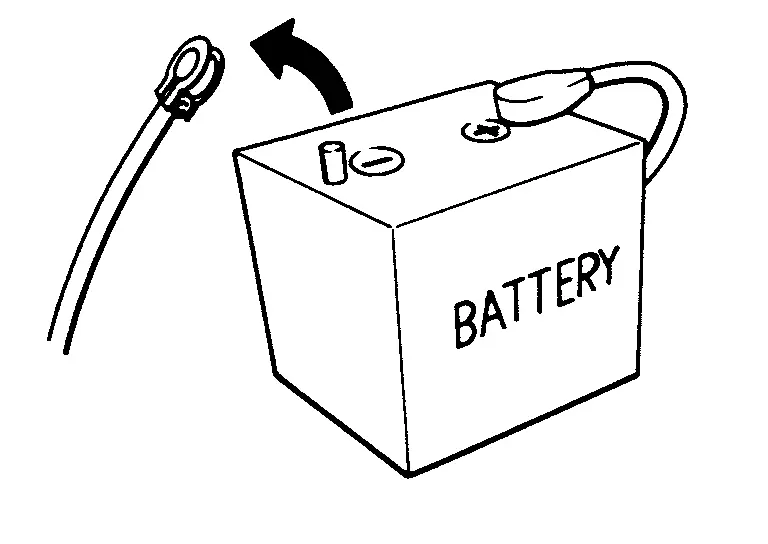
HOW TO DISCONNECT 12V BATTERY TERMINAL
Disconnect 12V battery terminal according to instruction described below.
-
Open the hood.
-
Turn ignition switch to the ON position.
-
Turn ignition switch to the OFF position with the driver side door opened.
-
Get out of the Nissan Ariya vehicle and close the driver side door.
-
Wait at least 3 minutes.
CAUTION:
While waiting, never operate the Nissan Ariya vehicle such as locking, opening, and closing doors. Violation of this caution results in the activation of ACC power supply according to the Auto ACC function.
-
Remove 12V battery terminal.
CAUTION:
After installing 12V battery, always check self-diagnosis results of all ECUs and erase DTC.
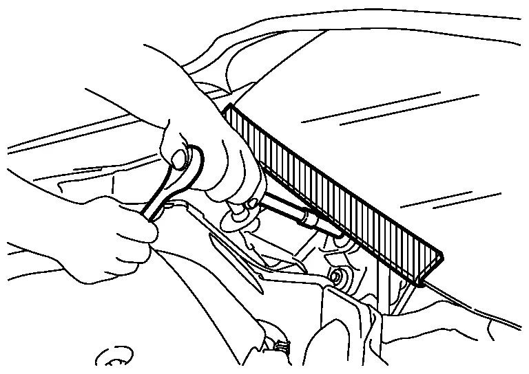
Precautions for Procedure Without Cowl Top Cover
PRECAUTIONS FOR PROCEDURE WITHOUT COWL TOP COVER : Precautions
When performing the procedure after removing cowl top cover, cover the lower end of windshield with urethane, etc to prevent damage to windshield.
On Board Diagnostic (obd) System
On Board Diagnostic (OBD) System of Engine and CVTF
The ECM has an on board diagnostic system. It will light up the malfunction indicator lamp (MIL) to warn the driver of a malfunction causing emission deterioration.
CAUTION:
-
Be sure to place the ignition switch in the OFF position and disconnect the negative battery cable before any repair or inspection work. The open/short circuit of related switches, sensors, solenoid valves, etc. will cause the MIL to light up.
-
Be sure to connect and lock the connectors securely after work. A loose (unlocked) connector will cause the MIL to light up due to the open circuit. (Be sure the connector is free from water, grease, dirt, bent terminals, etc.)
-
Certain systems and components, especially those related to OBD, may use a new style slide-locking type harness connector. For description and how to disconnect.
-
Be sure to route and secure the harnesses properly after work. The interference of the harness with a bracket, etc. may cause the MIL to light up due to the short circuit.
-
Be sure to connect rubber tubes properly after work. A misconnected or disconnected rubber tube may cause the MIL to light up due to the malfunction of the EVAP system or fuel injection system, etc.
-
Be sure to erase the unnecessary malfunction information (repairs completed) from the ECM and TCM (Transmission control module) before returning the Nissan Ariya vehicle to the customer.
General Precautions
GENERAL PRECAUTIONS : Precautions
-
Always use a 12 volt battery as power source.
-
Do not attempt to disconnect battery cables while engine is running.
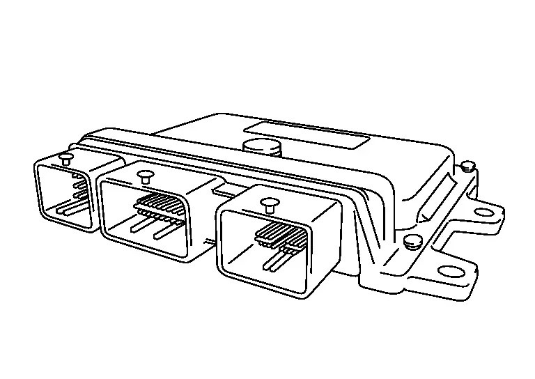
-
Before connecting or disconnecting the ECM harness connector, place the ignition switch in the OFF position and disconnect negative battery cable. Failure to do so may damage the ECM because battery voltage is applied to ECM even if ignition switch is placed in the OFF position.
-
Before removing parts, place the ignition switch in the OFF position and then disconnect battery ground cable.
-
Do not disassemble ECM.
-
If a battery cable is disconnected, the memory will return to the ECM value.
The ECM will now start to self-control at its initial value. Engine operation can vary slightly when the terminal is disconnected. However, this is not an indication of a malfunction. Do not replace parts because of a slight variation.
-
If the battery is disconnected, the following emission-related diagnostic information will be lost within 24 hours.
-
Diagnostic trouble codes
-
1st trip diagnostic trouble codes
-
Freeze frame data
-
1st trip freeze frame data
-
System readiness test (SRT) codes
-
Test values
-
-
When connecting or disconnecting pin connectors into or from ECM, take care not to damage pin terminals (bend or break).
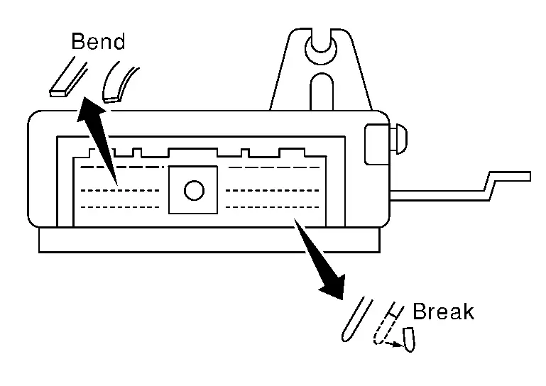
Make sure that there are not any bends or breaks on ECM pin terminal, when connecting pin connectors.
-
Securely connect ECM harness connectors.
A poor connection can cause an extremely high (surge) voltage to develop in coil and condenser, thus resulting in damage to ICs.
-
Keep engine control system harness at least 10 cm (4 in) away from adjacent harness, to prevent engine control system malfunctions due to receiving external noise, degraded operation of ICs, etc.
-
Keep engine control system parts and harness dry.
-
Before replacing ECM, perform ECM Terminals and Reference Value inspection and make sure ECM functions properly. Refer to Values On The Diagnosis Tool.
-
Handle mass air flow sensor carefully to avoid damage.
-
Do not clean mass air flow sensor with any type of detergent.
-
Do not disassemble electric throttle control actuator.
-
Even a slight leak in the air intake system can cause serious incidents.
-
Do not shock or jar the camshaft position sensor (PHASE), crankshaft position sensor (POS).
-
After performing each TROUBLE DIAGNOSIS, perform DTC CONFIRMATION PROCEDURE or Component Function Check. The DTC should not be displayed in the DTC Confirmation Procedure if the repair is completed. The Component Function Check should be a good result if the repair is completed.
-
When measuring ECM signals with a circuit tester, never allow the two tester probes to contact.
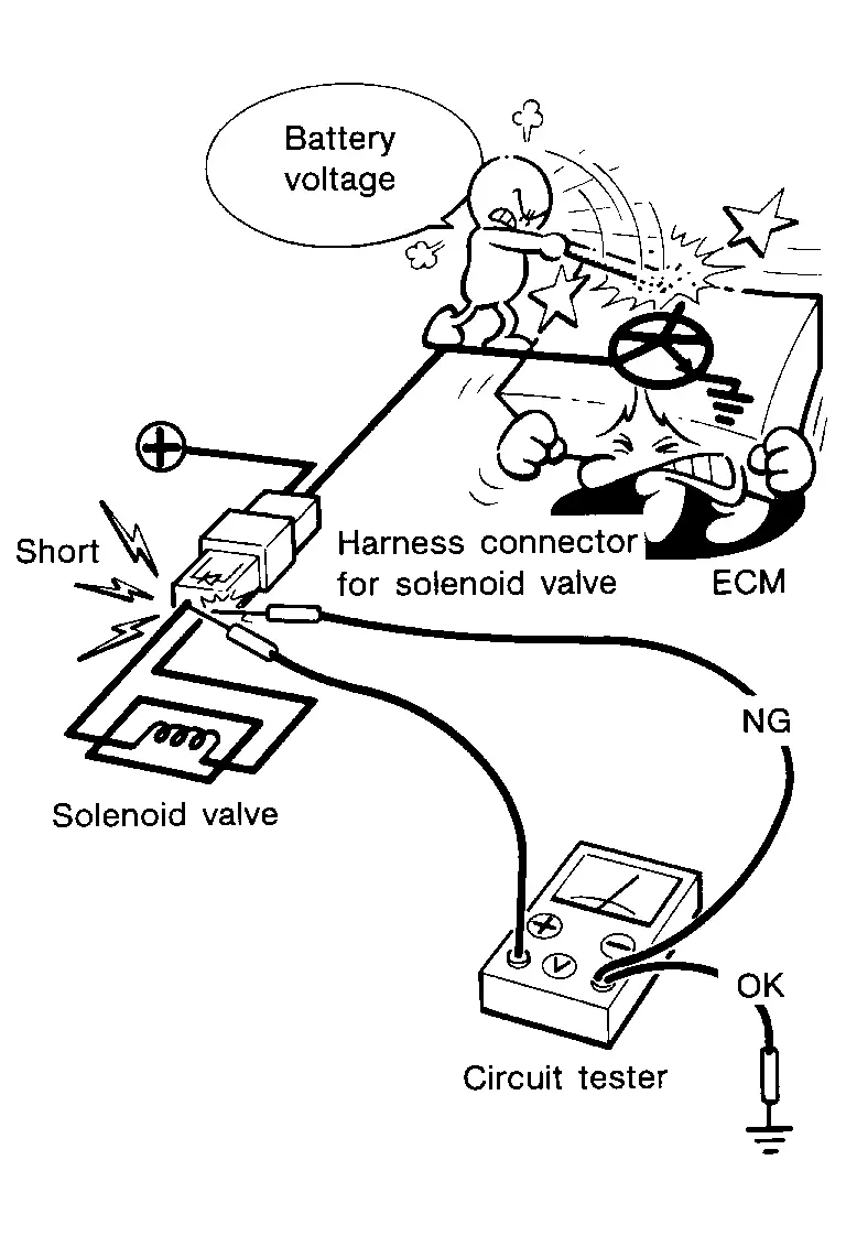
Accidental contact of probes will cause a short circuit and damage the ECM power transistor.
-
Do not operate fuel pump when there is no fuel in lines.
-
Tighten fuel hose clamps to the specified torque.
-
Do not depress accelerator pedal when starting.
-
Immediately after starting, do not rev up engine unnecessarily.
-
Do not rev up engine just prior to shutdown.
-
When installing C.B. ham radio or a mobile phone, be sure to observe the following as it may adversely affect electronic control systems depending on installation location.
-
Keep the antenna as far as possible from the electronic control units.
-
Keep the antenna feeder line more than 20 cm (8 in) away from the harness of electronic controls.
Do not let them run parallel for a long distance.
-
Adjust the antenna and feeder line so that the standing-wave ratio can be kept smaller.
-
Be sure to ground the radio to Nissan Ariya vehicle body.
-
Other materials:
Led Headlamp. Service Data and Specifications (sds). Service Data and Specifications (sds)
Service Data and Specifications (sds)
Bulb Specifications
Item Type Wattage (W)
Headlamp
Headlamp (Hi)
LED
ÔÇö
Headlamp (Lo)
LED
ÔÇö
Front combination lamp [front turn signal lamp (bulb type)]
Front turn signal lamp
7444NA
28/8W
Parking lamp/Daytime run ...
P2123 App Sensor
DTC Description
DTC DETECTION LOGIC DTC
CONSULT screen terms
(Trouble diagnosis content)
DTC detection condition
P2123
00
APP SEN 1/CIRC
(Throttle/Pedal position sensor/switch D circuit high)
Diagnosis condition
Engine running at idle
Signal (terminal)
Accelerator ...
System Description. System
System Description (Heated Steering Wheel)
SYSTEM DIAGRAMThe
heated steering wheel switch controls the heated steering wheel relay.
When the heated steering wheel switch is turned on, the heated steering
wheel relay is energized and the heated steering wheel system will
operate. The heated ...