Nissan Rogue (T33) 2021-Present Service Manual: Kr15ddt :: Precaution
Precaution for Procedure without Cowl Top Cover
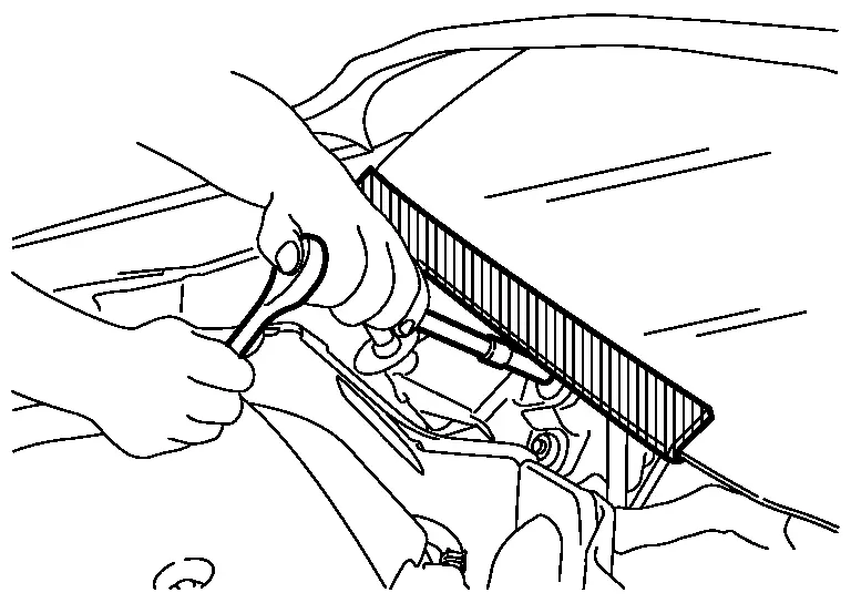
When performing the procedure after removing cowl top cover, cover the lower end of windshield with urethane, etc to prevent damage to windshield.
Precautions for Removing Battery Terminal
-
With the adoption of Auto ACC function, ACC power is automatically supplied by operating the Intelligent Key or remote keyless entry or by opening/closing the driver side door. In addition, ACC power is supplied even after the ignition switch is in the OFF position, i.e. ACC power is supplied for a certain fixed time.
-
When disconnecting the 12V battery terminal, place the ignition switch in the OFF position before disconnecting the 12V battery terminal, observing ŌĆ£How to disconnect 12V battery terminalŌĆØ described below.
 NOTE:
NOTE:
Some ECUs operate for a certain fixed time even after ignition switch is in the OFF position and ignition power supply is stopped. If the battery terminal is disconnected before ECU stops, accidental DTC detection or ECU data damage may occur.
-
For Nissan Ariya vehicles with the 2-batteries, be sure to connect the main battery and the sub battery before placing the ignition switch in the ON position.
NOTE:
If the ignition switch is in the ON position with any one of the terminals of main battery and sub battery disconnected, then DTC may be detected.
-
After installing the 12V battery, always check "Self Diagnosis Result" of all ECUs and erase DTC.
NOTE:
The removal of 12V battery may cause a DTC detection error.
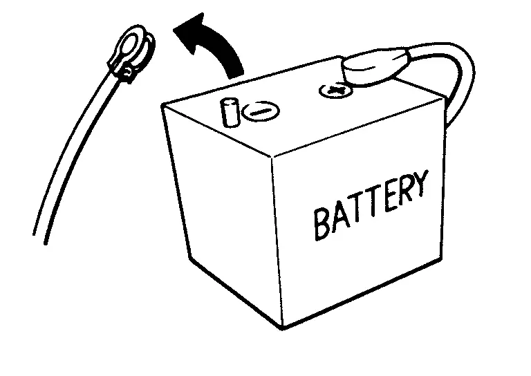
HOW TO DISCONNECT 12V BATTERY TERMINAL
Disconnect 12V battery terminal according to instruction described below.
-
Open the hood.
-
Place the ignition switch in the ON position.
-
Place the ignition switch in the OFF position with the driver side door opened.
-
Get out of the Nissan Ariya vehicle and close the driver side door.
-
Wait at least 3 minutes.
CAUTION:
While waiting, never operate the Nissan Ariya vehicle such as locking, opening, and closing doors. Violation of this caution results in the activation of ACC power supply according to the Auto ACC function.
-
Remove 12V battery terminal.
CAUTION:
After installing 12V battery, always check self-diagnosis results of all ECUs and erase DTC.
Precaution for Supplemental Restraint System (SRS) "AIR BAG" and "SEAT BELT PRE-TENSIONER"
The Supplemental Restraint System such as ŌĆ£AIR BAGŌĆØ and ŌĆ£SEAT BELT PRE-TENSIONERŌĆØ, used along with a front seat belt, helps to reduce the risk or severity of injury to the driver and front passenger for certain types of collisions.
Information necessary to service the system safely is included in the ŌĆ£SRS AIR BAGŌĆØ and ŌĆ£SEAT BELTŌĆØ sections of this Service Manual.
WARNING:
Always observe the following items for preventing accidental activation:
-
To avoid rendering the SRS inoperative, which could increase the risk of personal injury or death in the event of a collision that would result in air bag inflation, it is recommended that all maintenance and repair be performed by an authorized NISSAN/INFINITI dealer.
-
Improper repair, including incorrect removal and installation of the SRS, can lead to personal injury caused by unintentional activation of the system. For removal of Spiral Cable and Air Bag Module, see ŌĆ£SRS AIR BAGŌĆØ.
-
Never use electrical test equipment on any circuit related to the SRS unless instructed to in this Service Manual. SRS wiring harnesses can be identified by yellow and/or orange harnesses or harness connectors.
PRECAUTIONS WHEN USING POWER TOOLS (AIR OR ELECTRIC) AND HAMMERS
WARNING:
Always observe the following items for preventing accidental activation:
-
When working near the Air Bag Diagnosis Sensor Unit or other Air Bag System sensors with the ignition/power switch ON or engine running, never use air or electric power tools or strike near the sensor(s) with a hammer. Heavy vibration could activate the sensor(s) and deploy the air bag(s), possibly causing serious injury.
-
When using air or electric power tools or hammers, always switch the ignition/power switch OFF, disconnect the 12V battery or batteries, and wait at least 3 minutes before performing any service.
Precautions For Engine Service
DISCONNECTING FUEL PIPING
-
Before starting work, check no fire or spark producing items are in the work area.
-
Release fuel pressure before disconnecting and disassembly.
-
After disconnecting pipes, plug openings to stop fuel leakage.
DRAINING ENGINE COOLANT
Drain engine coolant and engine oil when the engine is cooled.
INSPECTION, REPAIR AND REPLACEMENT
-
Before repairing or replacing, thoroughly inspect parts. Inspect new replacement parts in the same way, and replace if necessary.
-
When replacing or inspecting air cleaner element, remove foreign matter inside air duct, on air cleaner element surface, and inside cleaner case.
REMOVAL AND DISASSEMBLY
-
When instructed to use SST, use specified tools. Always be careful to work safely, avoid forceful or uninstructed operations.
-
Exercise maximum care to avoid damage to mating or sliding surfaces.
-
Dowel pins are used for several parts alignment. When replacing and reassembling parts with dowel pins, check that dowel pins are installed in the original position.
-
Must cover openings of engine system with a tape or equivalent, to seal out foreign materials.
-
Mark and arrange disassembly parts in an organized way for easy troubleshooting and reassembly.
-
When loosening nuts and bolts, as a basic rule, start with the one furthest outside, then the one diagonally opposite, and so on. If the order of loosening is specified, do exactly as specified. Power tools may be used in the step.
ASSEMBLY AND INSTALLATION
-
Use torque wrench to tighten bolts or nuts to specification.
-
When tightening nuts and bolts, as a basic rule, equally tighten in several different steps starting with the ones in center, then ones on inside and outside diagonally in this order. If the order of tightening is specified, do exactly as specified.
-
Before removing or installing any intake-system-related parts, thoroughly clean them to prevent foreign matter from entering inside engine.
-
Replace with new gasket, packing, oil seal or O-ring.
-
Thoroughly wash, clean, and air-blow each part. Carefully check engine oil or engine coolant passages for any restriction and blockage.
-
Avoid damaging sliding or mating surfaces. Completely remove foreign materials such as cloth lint or dust. Before assembly, oil sliding surfaces well.
-
After disassembling, or exposing any internal engine parts, change engine oil and replace oil filter with a new one.
-
Release air within route when refilling after draining engine coolant.
-
After repairing, start the engine and increase engine speed to check engine coolant, fuel, engine oil, and exhaust gases for leakage.
Precaution for Handling High Pressure Fuel System
-
High pressure fuel system components are between high pressure fuel pump and fuel injector.
-
Always release fuel pressure and never start the engine when performing removal and installation.
-
When removing or installing parts without releasing fuel pressure, fuel may be splashed and, if fuel contacts skin or eyes, it may cause inflammation.
Parts Requiring Angle Tightening
-
Use the angle wrench [SST: KV10112100 (BT8653ŌĆōA)] for the final tightening of the following engine parts:
-
Camshaft sprocket (INT) bolt
-
Cylinder head bolts
-
Main bearing cap bolts
-
Connecting rod cap bolts
-
Crankshaft pulley bolt (No the angle wrench is required as bolt flange is provided with notches for angle tightening)
-
-
Do not use a torque value for final tightening.
-
The torque value for these parts are for a preliminary step.
-
Ensure thread and seat surfaces are clean and coated with engine oil.
Liquid Gasket
REMOVAL OF LIQUID GASKET SEALING
-
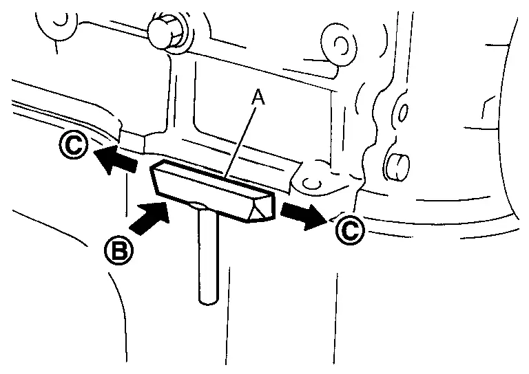
After removing mounting nuts and bolts, separate the mating surface using the seal cutter [SST: KV10111100 (NI-37228)] (A) and remove old liquid gasket sealing.
CAUTION:
Never damage the mating surfaces.
-
Tap the seal cutter [SST: KV10111100 (NI-37228)] to insert it
 , and then slide it
  by tapping on the side as shown in the figure.
 -
In areas where the seal cutter [SST: KV10111100 (NI-37228)] is difficult to use, lightly tap the parts using a plastic hammer to remove it.
CAUTION:
If for some unavoidable reason tool such as a screwdriver is used, be careful not to damage the mating surfaces.
LIQUID GASKET APPLICATION PROCEDURE
-
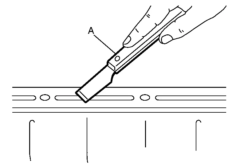
Using a scraper (A), remove old liquid gasket adhering to the liquid gasket application surface and the mating surface.
-
Remove liquid gasket completely from the groove of the liquid gasket application surface, mounting bolts, and bolt holes.
-
-
Wipe the liquid gasket application surface and the mating surface with white gasoline (lighting and heating use) to remove adhering moisture, grease and foreign materials.
-
Attach liquid gasket tube to the tube presser (commercial service tool).
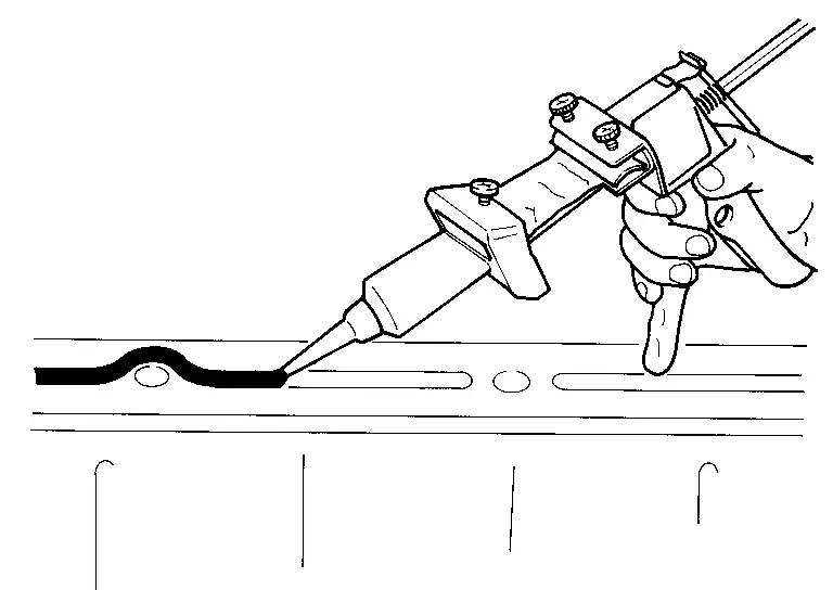
Use Genuine Liquid Gasket or equivalent.
-
Apply liquid gasket without gaps to the specified location according to the specified dimensions.
-
If there is a groove for liquid gasket application, apply liquid gasket to the groove.
-
As for bolt holes
, normally
apply liquid gasket inside the holes. Occasionally, it should be applied
outside the holes. Check to read the text of this manual.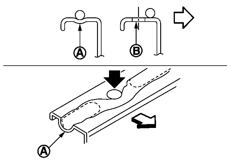

: Groove 
: Inside -
Within five minutes of liquid gasket application, install the mating component.
-
If liquid gasket protrudes, wipe it off immediately.
-
Do not retighten mounting bolts or nuts after the installation.
-
After 30 minutes or more have passed from the installation, fill engine oil and engine coolant.
CAUTION:
If there are specific instructions in this manual, observe them.
-
Special Cautions to Ensure the Safe Disposal of Sodium-filled Exhaust Valves
Handling and disposal of sodium-filled exhaust valves requires special care and consideration. Under conditions such as breakage with subsequent contact with water, metal sodium which lines the inner portion of exhaust valve will react violently, forming sodium hydroxide and hydrogen which may result in an explosion. Sodium-filled exhaust valve is identified on the top of its stem as shown in illustration.
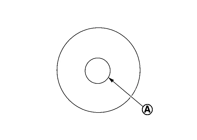
| Identification mark of sodium-filled exhaust valve |
: NA3 | |
DEALER DISPOSAL INSTRUCTIONS
CAUTION:
-
Use approved shatter-resistant eye protection when performing this procedure.
-
Perform this and all subsequent disposal work procedures in an open room, away from flammable liquids. Keep a fire extinguisher, rated at least 10 ABC, in close proximity to the work area.
-
Be sure to wear rubber gloves when performing the following operations.
-
Make sure the resultant (high alkalinity) waste water does not contact your skin. If the waste water does contact you, wash the contacted area immediately with large quantities of water.
-
Dealers should check their respective state and local regulations concerning any chemical treatment or waste water discharge permits which may be required to dispose of the resultant (high alkalinity) waste water.
-
Clamp valve stem in a vice.
-
The valve has a specially-hardened surface. To cut through it, first remove a half-round section, approximately 30 mm (1.18 in) long using air-powered grinder until black color is removed and silver color appears.
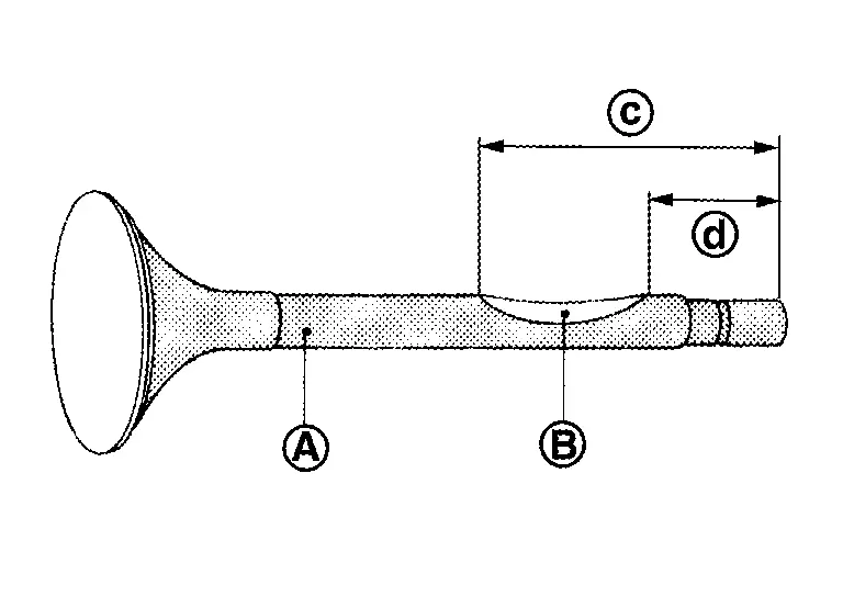
: Black color : Silver color 
: 63 mm (2.48 in) 
: 33 mm (1.30 in) -
Use hacksaw to cut through approximately half the diameter of valve stem. Make the serration at a point 40 mm (1.57 in) from the end of valve stem.
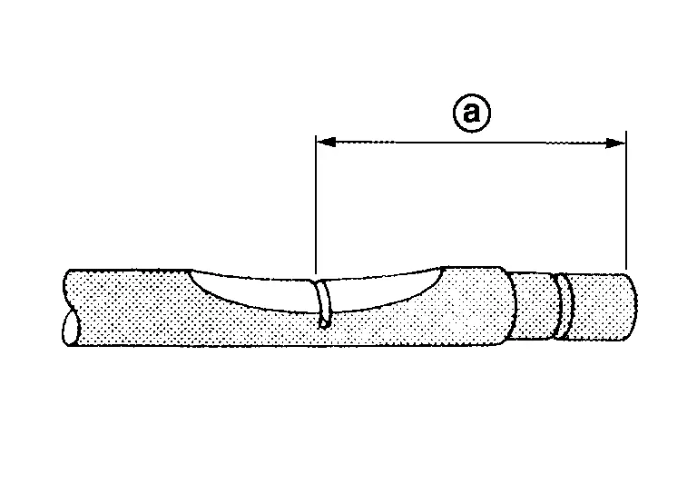

: 48 mm (1.89 in) -
Cover the serrated end of the valve with a large shop towel
. Strike the valve face end with a hammer, separating it into two pieces.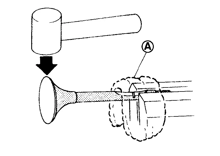
-
Fill a bucket
(such as a 20  oil can) with at least 10
(2-1/4 lmp gal) of water. Carefully place the alreadycut (serrated)
valves into the water one-at-a-time using a set of large tweezers and
quickly move away at least 2.7 m (9 ft).
oil can) with at least 10
(2-1/4 lmp gal) of water. Carefully place the alreadycut (serrated)
valves into the water one-at-a-time using a set of large tweezers and
quickly move away at least 2.7 m (9 ft).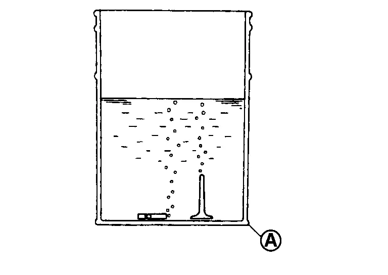
-
The valves should be placed in a standing position as shown in the illustration to allow complete reaction. After the bubbling action has subsided, additional valves can be placed into the bucket allowing each subsequent chemical reaction to subside. However, no more than 8 valves should be placed in the same 10
(2-1/4 lmp gal) amount of water. The complete chemical reaction may take
as long as 4 to 5 hours. Remove the valves using a set of large
tweezers after the chemical reaction has stopped. Afterwards, valves can
be disposed as ordinary scrap.
Other materials:
Periodic Maintenance. Front Disc Brake
Brake Pad
Inspection and Adjustment
INSPECTIONCheck brake pad wear thickness from an inspection hole on cylinder body. Check using a scale if necessary. Wear thickness
: Refer to Front Disc Brake.
ADJUSTMENTBurnish contact surfaces
between disc rotor and brake pads according to the follow ...
P2615 Intake Camshaft Position Sensor
DTC Description
DTC DETECTION LOGIC DTC
CONSULT screen terms
(Trouble diagnosis content)
DTC detection condition
P2615
00
A camshaft posi signal B1
(Camshaft A Position Signal Output Circuit Low Bank 1)
Diagnosis condition
Engine running at idle
Signal (terminal)
...
P2122 App Sensor
DTC Description
DTC DETECTION LOGIC DTC
CONSULT screen terms
(Trouble diagnosis content)
DTC detection condition
P2122
00
APP SEN 1/CIRC
(Throttle/Pedal position sensor/switch D circuit low)
Diagnosis condition
Engine running at idle
Signal (terminal)
Accelerator ...