Nissan Rogue (T33) 2021-Present Service Manual: Intelligent Around View Monitor :: Removal and Installation
Around View Monitor Control Unit
Removal and Installation
REMOVAL
CAUTION:
Perform the ŌĆ£ADDITIONAL SERVICE WHEN REPLACING AROUND VIEW MONITOR CONTROL UNITŌĆØ before replacing around view monitor control unit. Refer to Description.
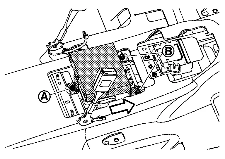
Remove the center console assembly. Refer to Removal and Installation.
Remove the around view monitor control unit mounting bolt  and nuts
  .
.
 |
: Nissan Ariya Vehicle front |
Disconnect the connectors to remove the around view monitor control unit from the Nissan Ariya vehicle.
INSTALLATION
Installation is the reverse order of removal.
CAUTION:
Perform the ŌĆ£ADDITIONAL SERVICE WHEN REPLACING AROUND VIEW MONITOR CONTROL UNITŌĆØ after replacing around view monitor control unit. Refer to Description.
Front Camera
Removal and Installation
REMOVAL
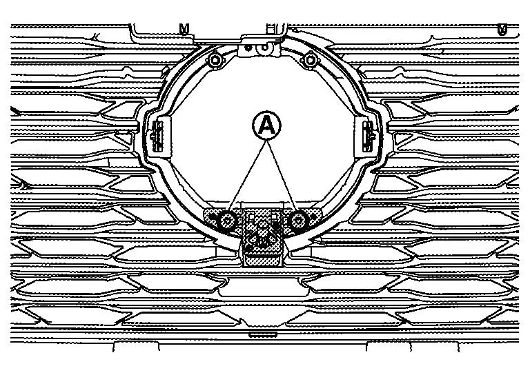
Remove the distance sensor bracket assembly. Refer to Removal and Installation.
Remove the front camera mounting screws , then remove the front camera.
INSTALLATION
Installation in the reverse order of removal.
Perform camera image calibration. Refer to Work Procedure (WITHOUT ProPILOT Assist 2.1) or Work Procedure (WITH ProPILOT Assist 2.1).
CAUTION:
Perform the calibration and perform the writing to the around view monitor control unit when removing and replacing each camera, removing the camera mounting parts (front grille, door mirror, etc.) and replacing the around view monitor control unit.
Rear Camera
Removal and Installation
REMOVAL
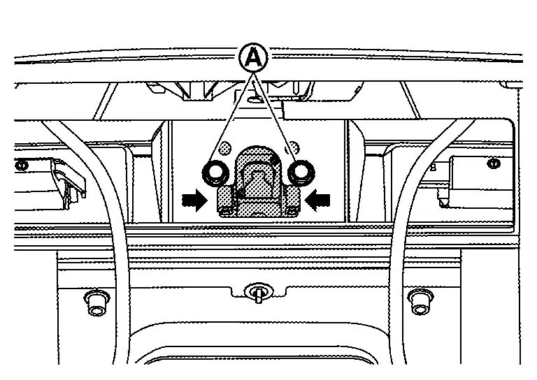
Remove the back door inner finisher. Refer to Removal and Installation.
Remove the rear camera mounting bolts , And then push the pawls in the direction of the arrow in the figure to remove the rear camera.
INSTALLATION
Installation is in the reverse order of removal.
Perform camera image calibration. Refer to Work Procedure (WITHOUT ProPILOT Assist 2.1) or Work Procedure (WITH ProPILOT Assist 2.1).
CAUTION:
Perform the calibration and perform the writing to the around view monitor control unit when removing and replacing each camera, removing the camera mounting parts (front grille, door mirror, etc.) and replacing the around view monitor control unit.
Side Camera
Removal and Installation
REMOVAL
-
Remove the door mirror finisher. Refer to Disassembly and Assembly.
-
Remove the side camera mounting screw
, And then remove the side camera.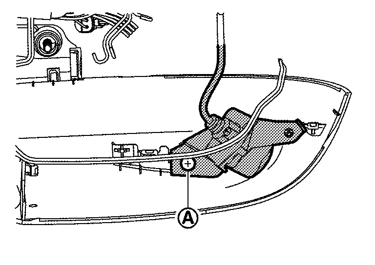
INSTALLATION
Installation is in the reverse order of removal.
Perform camera image calibration. Refer to Work Procedure (WITHOUT ProPILOT Assist 2.1) or Work Procedure (WITH ProPILOT Assist 2.1).
CAUTION:
Perform the calibration and perform the writing to the around view monitor control unit when removing and replacing each camera, removing the camera mounting parts (front grille, door mirror, etc.) and replacing the around view monitor control unit.
Other materials:
Additional Service When Replacing Side Radar
Work Procedure
Always perform the side radar configuration after replacing the side radar.SIDE RADAR CONFIGURATION
Perform saving vehicle internal information according to "Replace ECU" in CONSULT Operation Manual.
>>
GO TO 2.
SIDE RADAR ALIGNMENT
Perform the side radar alignment with ...
P023a Charge Air Cooler Cooling Electric Water Pump
DTC Description
DTC DETECTION LOGIC DTC
CONSULT screen terms
(Trouble diagnosis content)
DTC detection condition
P023A
00
Charged air cooler coolant pump
(Charge Air Cooler Coolant Pump Control Circuit/Open)
Diagnosis condition
Engine running at idle
Warm-up con ...
P0420 Three Way Catalyst Function
DTC Description
The ECM monitors the switching frequency ratio of air fuel ratio (A/F) sensor 1 and heated oxygen sensor 2.A
three way catalyst (manifold) with high oxygen storage capacity will
indicate a low switching frequency of heated oxygen sensor 2. As oxygen
storage capacity decreases, ...