Nissan Rogue (T33) 2021-Present Service Manual: Intelligent Around View Monitor :: Ecu Diagnosis Information. Around View Monitor Control Unit
Around View Monitor Control Unit
With 8" Color Display
Reference Value
VALUES ON THE DIAGNOSIS TOOL
 NOTE:
NOTE:
The following table includes information (items) inapplicable to this Nissan Ariya vehicle. For information (items) applicable to this vehicle, refer to CONSULT display items.
| Display Item | Remarks | Value/Status | |
|---|---|---|---|
|
Power supply state [State1/State2/State3/ State4/State5/State6/State7/ State8/State9/State10/ State11/State12] |
[Ignition switch ON] | sleep mode | State1 |
| — | State2 | ||
| Cutoff Pending | State3 | ||
| Auto ACC ON | State4 | ||
| — | State5 | ||
| Ignition switch ON | State6 | ||
| State7 | |||
| READY state | State8 | ||
| Automatic brake hold OFF | State9 | ||
| Automatic brake hold ON | State10 | ||
| — | State11 | ||
| — | State12 | ||
| GADE | Cranking or ignition switch OFF and auto ACC ON | Sleep or crank malfunction disable | |
| Ignition switch OFF and auto ACC ON | Auto ACC malfunction disable | ||
| Ignition switch OFF and auto ACC ON (When the battery voltage is low) | All malfunction disable | ||
| Ignition switch ON and auto ACC ON (READY state ) | All malfunction enable | ||
| When software is automatically updated | Firmware update Over The Air software malfunction | ||
|
Shift position [Parking/Neutral/Rear/Drive/Unavailable] |
While driving | Displays shift position | |
|
REVERSE SIGNAL [On/Off] |
[Ignition switch ON] | R position | On |
| Other than R position | Off | ||
|
CAMERA SWITCH SIGNAL [On/Off] |
[Ignition switch ON] | When camera switch signal is input | On |
| Other than the above | Off | ||
|
CAMERA OFF SIGNAL [On/Off] |
[Ignition switch ON] | Off | |
|
REAR CAMERA IMAGE SIGNAL [OK/NG] |
[Ignition switch ON] | When rear camera image signal input status is normal | OK |
| When rear view camera image signal input status is not normal | NG | ||
| Rear camera communication status [OK/NG] | [Ignition switch ON] | When communication status with rear camera is normal | OK |
| When communication status with rear camera is not normal | NG | ||
|
Rear camera communication line [OK/NG] |
[Ignition switch ON] | When communication line with rear camera is normal | OK |
| When communication line with rear camera is not normal | NG | ||
|
Front camera image signal [OK/NG] |
[Ignition switch ON] | When front camera image signal input status is normal | OK |
| When front camera image signal input status is not normal | NG | ||
|
Front camera communication status [OK/NG] |
[Ignition switch ON] | When communication status with front camera is normal | OK |
| When communication status with front camera is not norma | NG | ||
|
Front camera communication line [OK/NG] |
[Ignition switch ON] | When communication line with front camera is normal | OK |
| When communication line with front camera is not normal | NG | ||
|
Left camera image signal [OK/NG] |
[Ignition switch ON] | When side camera LH image signal input status is normal | OK |
| When side camera LH image signal input status is not normal | NG | ||
|
Left camera communication status [OK/NG] |
[Ignition switch ON] | When communication status with side camera LH is normal | OK |
| When communication status with side camera LH is not normal | NG | ||
|
Left camera line [OK/NG] |
[Ignition switch ON] | When communication line with side camera LH is normal | OK |
| When communication line with side camera LH is not normal | NG | ||
|
Right camera image signal [OK/NG] |
[Ignition switch ON] | When side camera RH image signal input status is normal | OK |
| When side camera RH image signal input status is not normal | NG | ||
|
Right camera communication status [OK/NG] |
[Ignition switch ON] | When communication status with side camera RH is normal | OK |
| When communication status with side camera RH is not normal | NG | ||
|
Right camera line [OK/NG] |
[Ignition switch ON] | When communication line with side camera RH is normal | OK |
| When communication line with side camera RH is not normal | NG | ||
|
Folding motor voltage 1 [Low/N/High/RESERVE] |
[Ignition switch ON] | Passenger side door mirror is in retracted status | Low |
| Passenger side door mirror is in expanded status | High | ||
|
Folding motor voltage 2 [Low/N/High/RESERVE] |
[Ignition switch ON] | Passenger side door mirror is in retracted status | High |
| Passenger side door mirror is in expanded status | Low | ||
|
Image output [Yes/None] |
[Ignition switch ON] | When camera image displayed | Yes |
|
Average Nissan Ariya vehicle speed [km/h] |
While driving | Input value of Nissan Ariya vehicle speed signal | |
|
VehicleSpeed1 [km/h] |
While driving | Input value of Nissan Ariya vehicle speed signal | |
TERMINAL LAYOUT
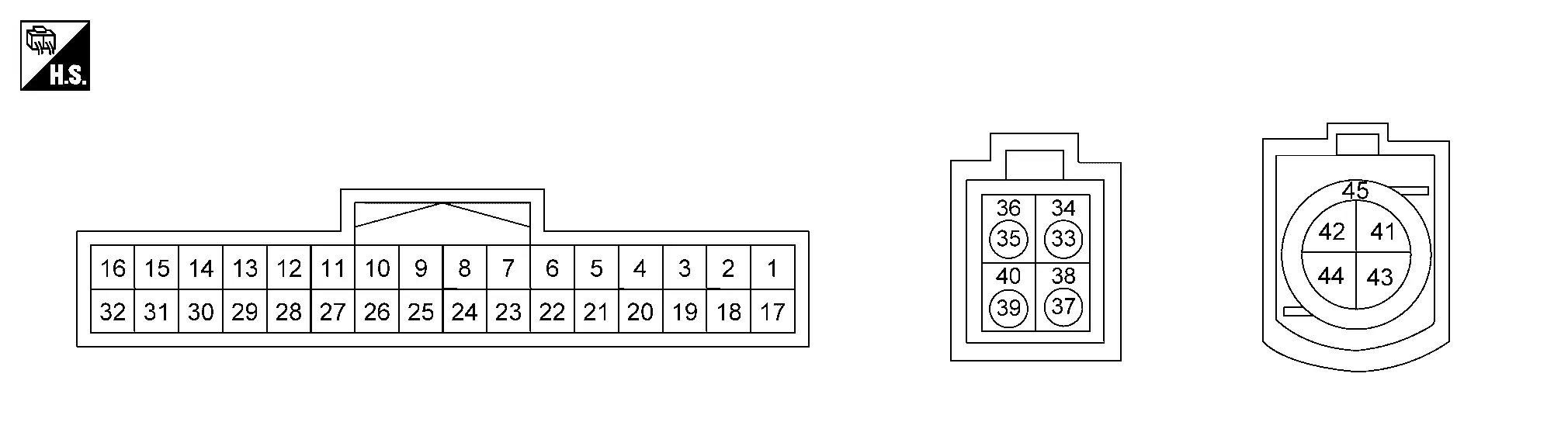
PHYSICAL VALUES
|
Terminal (Wire color) | Description | Condition |
Reference value (Approx.) | ||
|---|---|---|---|---|---|
| + | – | Signal name | Input/Output | ||
|
3 (BR) |
— | CAN-High | Input/Output | — | — |
|
5 (Y) |
— | CAN-Low | Input/Output | — | — |
|
6 (BR) |
— | CAN-High | Input/Output | — | — |
|
7 (L)1 (P)2 |
— | Not used | — | — | — |
|
8 (V) |
— | Not used | — | — | — |
|
15 (G)1 (W)2 |
— | Not used | — | — | — |
|
16 (B) |
Ground | Ground | — | [Ignition switch ON] | 0 V |
|
17 (LA/G) |
16 (B) |
ACC power supply | Input | [Ignition switch ACC] | Battery voltage |
|
20 (P) |
— | CAN-Low | Input/Output | — | — |
|
21 (BR) |
— | CAN-High | Input/Output | — | — |
|
23 (W) |
— | CAN-Low | Input/Output | — | — |
|
24 (SB) |
— | Not used | — | — | — |
|
32 (B) |
— | Not used | — | — | — |
|
33 (B) |
34 (Shield) |
LVDS (Side camera LH) | Input/Output | — | — |
|
35 (B) |
36 (Shield) |
LVDS (Side camera RH) | Input/Output | — | — |
|
37 (B) |
38 (Shield) |
LVDS (Rear camera) | Input/Output | — | — |
|
39 (B) |
40 (Shield) |
LVDS (Front camera) | Input/Output | — | — |
|
43 (L) |
42 (R) |
LVDS | Input/Output | — | — |
|
45 (Shield) |
— | LVDS shield | — | — | — |
1: USA production
2: Japan production
Fail-safe
|
DTC Display contents of CONSULT | Fail-safe condition |
|---|---|
| B2A04-51: Around view monitor control unit |
|
| B2A05-44: Around view monitor control unit | MOD (Moving Object Detection) function is stopped. |
| B2A05-45: Around view monitor control unit | |
| B2A05-46: Around view monitor control unit | |
| B2A05-49: Around view monitor control unit | |
| B2A05-55: Around view monitor control unit |
|
| B2A07-86: Steering angle sensor |
|
| B2A0A-86: Sonar control unit | Parking sensor error is displayed. |
| B2A0B-86: ABS actuator and electric unit |
|
| B2A0C-86: TCM |
|
| B2A1A-13: Rear camera |
|
| B2A1A-31: Rear camera |
|
| B2A1B-13: Right camera |
|
| B2A1B-31: Right camera |
|
| B2A1C-13: Front camera |
|
| B2A1C-31: Front camera |
|
| B2A1D-13: Left camera |
|
| B2A1D-31: Left camera |
|
| B2A1F-16: Camera power supply |
|
| B2A2C-A2: Power supply | |
| B2A2C-A3: Power supply | |
| U2141-87:CAN comm err (TCM) |
|
| U2148-87: CAN comm err (brake control unit) |
|
| U214E-87: CAN comm err (combination meter) | MOD (Moving Object Detection) settings cannot be changed. |
| U214F-87: CAN comm err (BCM) |
|
| U2152-87: CAN comm err (ADAS control unit) | ― |
| U2154-87: CAN comm err (MIU) |
|
| U2156-87: CAN comm err (steering angel sensor) |
|
| U215B-87: CAN comm err (IPDM E/R) | ― |
| U2165-87: CAN comm err (sonar) | Parking sensor error is displayed. |
| U2265-87: CAN comm err (sonar) | ― |
| U2354-87: CAN comm err (MIU) |
|
| U236E-87: CAN comm err (side radar) | Yellow frame of RCTA is not displayed. |
| U2A04-88: Comm Bus Off ITS1-FD |
|
| U2A05-88: Comm Bus Off ITS4-FD | |
| U2A08-88: Comm Bus Off ITS3-FD | ― |
| U1327-52: MAC Key update | |
| U1327-54: MAC Key update | |
| U214F-57 : CAN comm err (BCM) |
|
| U2152-57: CAN comm err (ADAS control unit) | ― |
| U2176-57 : CAN comm err (CCM) |
 display (red) is displayed (applicable for unmatched camera only).
 marking (Red) is displayed.
DTC Inspection Priority Chart
If multiple DTCs are detected simultaneously, check them one by one depending on the following DTC inspection priority chart.
| Priority | Detected items (DTC) |
|---|---|
| 1 |
|
| 2 | U1327-54: MAC Key update |
| 3 | U1327-52: MAC Key update |
| 4 |
|
| 5 |
|
| 6 |
|
DTC Index
Self diagnostic result
| DTC | CONSULT display | Refer to |
|---|---|---|
| B2A04-51 | Around view monitor control unit | DTC Description |
| B2A05-44 | Around view monitor control unit | DTC Description |
| B2A05-45 | Around view monitor control unit | DTC Description |
| B2A05-46 | Around view monitor control unit | DTC Description |
| B2A05-49 | Around view monitor control unit | DTC Description |
| B2A05-55 | Around view monitor control unit | DTC Description |
| B2A07-86 | Steering angle sensor | DTC Description |
| B2A0A-86 | Sonar control unit | DTC Description |
| B2A0B-86 | ABS actuator and electric unit | DTC Description |
| B2A0C-86 | TCM | DTC Description |
| B2A1A-13 | Rear camera | DTC Description |
| B2A1A-31 | Rear camera | DTC Description |
| B2A1B-13 | Right camera | DTC Description |
| B2A1B-31 | Right camera | DTC Description |
| B2A1C-13 | Front camera | DTC Description |
| B2A1C-31 | Front camera | DTC Description |
| B2A1D-13 | Left camera | DTC Description |
| B2A1D-31 | Left camera | DTC Description |
| B2A1F-16 | Camera power supply | DTC Description |
| B2A2C-A2 | Power supply | DTC Description |
| B2A2C-A3 | Power supply | DTC Description |
Network-DTC
| DTC | CONSULT display | Refer to |
|---|---|---|
| U2141-87 | CAN comm err (TCM) | DTC Description |
| U2148-87 | CAN comm err (brake control unit) | DTC Description |
| U214E-87 | CAN comm err (combination meter) | DTC Description |
| U214F-87 | CAN comm err (BCM) | DTC Description |
| U2152-87 | CAN comm err (ADAS control unit) | DTC Description |
| U2154-87 | CAN comm err (MIU) | DTC Description |
| U2156-87 | CAN comm err (steering angel sensor) | DTC Description |
| U215B-87 | CAN comm err (IPDM E/R) | DTC Description |
| U2165-87 | CAN comm err (sonar) | DTC Description |
| U2265-87 | CAN comm err (sonar) | DTC Description |
| U2354-87 | CAN comm err (MIU) | DTC Description |
| U236E-87 | CAN comm err (side radar) | DTC Description |
| U2A04-88 | Comm Bus Off ITS1-FD | DTC Description |
| U2A05-88 | Comm Bus Off ITS4-FD | DTC Description |
| U2A08-88 | Comm Bus Off ITS3-FD | DTC Description |
MAC Diagnosis
| DTC | CONSULT display | Refer to |
|---|---|---|
| U1327-52 | MAC Key update | DTC Description |
| U1327-54 | MAC Key update | DTC Description |
| U214F-57 | CAN comm err (BCM) | DTC Description |
| U2152-57 | CAN comm err (ADAS control unit) | DTC Description |
| U2176-57 | CAN comm err (CCM) | DTC Description |
With 12.3" Color Display
Reference Value
VALUES ON THE DIAGNOSIS TOOL
NOTE:
The following table includes information (items) inapplicable to this Nissan Ariya vehicle. For information (items) applicable to this vehicle, refer to CONSULT display items.
| Display Item | Remarks | Value/Status | |
|---|---|---|---|
|
Power supply state [State1/State2/State3/ State4/State5/State6/State7/ State8/State9/State10/ State11/State12] |
[Ignition switch ON] | sleep mode | State1 |
| — | State2 | ||
| Cutoff Pending | State3 | ||
| Auto ACC ON | State4 | ||
| — | State5 | ||
| Ignition switch ON | State6 | ||
| State7 | |||
| READY state | State8 | ||
| Automatic brake hold OFF | State9 | ||
| Automatic brake hold ON | State10 | ||
| — | State11 | ||
| — | State12 | ||
| GADE | Cranking or ignition switch OFF and auto ACC ON | Sleep or crank malfunction disable | |
| Ignition switch OFF and auto ACC ON | Auto ACC malfunction disable | ||
| Ignition switch OFF and auto ACC ON (When the battery voltage is low) | All malfunction disable | ||
| Ignition switch ON and auto ACC ON (READY state ) | All malfunction enable | ||
| When software is automatically updated | Firmware update Over The Air software malfunction | ||
|
Shift position [Parking/Neutral/Rear/Drive/Unavailable] |
While driving | Displays shift position | |
|
REVERSE SIGNAL [On/Off] |
[Ignition switch ON] | R position | On |
| Other than R position | Off | ||
|
CAMERA SWITCH SIGNAL [On/Off] |
[Ignition switch ON] | When camera switch signal is input | On |
| Other than the above | Off | ||
|
CAMERA OFF SIGNAL [On/Off] |
[Ignition switch ON] | Off | |
|
REAR CAMERA IMAGE SIGNAL [OK/NG] |
[Ignition switch ON] | When rear camera image signal input status is normal | OK |
| When rear view camera image signal input status is not normal | NG | ||
| Rear camera communication status [OK/NG] | [Ignition switch ON] | When communication status with rear camera is normal | OK |
| When communication status with rear camera is not normal | NG | ||
|
Rear camera communication line [OK/NG] |
[Ignition switch ON] | When communication line with rear camera is normal | OK |
| When communication line with rear camera is not normal | NG | ||
|
Front camera image signal [OK/NG] |
[Ignition switch ON] | When front camera image signal input status is normal | OK |
| When front camera image signal input status is not normal | NG | ||
|
Front camera communication status [OK/NG] |
[Ignition switch ON] | When communication status with front camera is normal | OK |
| When communication status with front camera is not norma | NG | ||
|
Front camera communication line [OK/NG] |
[Ignition switch ON] | When communication line with front camera is normal | OK |
| When communication line with front camera is not normal | NG | ||
|
Left camera image signal [OK/NG] |
[Ignition switch ON] | When side camera LH image signal input status is normal | OK |
| When side camera LH image signal input status is not normal | NG | ||
|
Left camera communication status [OK/NG] |
[Ignition switch ON] | When communication status with side camera LH is normal | OK |
| When communication status with side camera LH is not normal | NG | ||
|
Left camera line [OK/NG] |
[Ignition switch ON] | When communication line with side camera LH is normal | OK |
| When communication line with side camera LH is not normal | NG | ||
|
Right camera image signal [OK/NG] |
[Ignition switch ON] | When side camera RH image signal input status is normal | OK |
| When side camera RH image signal input status is not normal | NG | ||
|
Right camera communication status [OK/NG] |
[Ignition switch ON] | When communication status with side camera RH is normal | OK |
| When communication status with side camera RH is not normal | NG | ||
|
Right camera line [OK/NG] |
[Ignition switch ON] | When communication line with side camera RH is normal | OK |
| When communication line with side camera RH is not normal | NG | ||
|
Folding motor voltage 1 [Low/N/High/RESERVE] |
[Ignition switch ON] | Passenger side door mirror is in retracted status | Low |
| Passenger side door mirror is in expanded status | High | ||
|
Folding motor voltage 2 [Low/N/High/RESERVE] |
[Ignition switch ON] | Passenger side door mirror is in retracted status | High |
| Passenger side door mirror is in expanded status | Low | ||
|
Image output [Yes/None] |
[Ignition switch ON] | When camera image displayed | Yes |
|
Average Nissan Ariya vehicle speed [km/h] |
While driving | Input value of Nissan Ariya vehicle speed signal | |
|
VehicleSpeed1 [km/h] |
While driving | Input value of Nissan Ariya vehicle speed signal | |
TERMINAL LAYOUT
Without ProPILOT Assist 2.1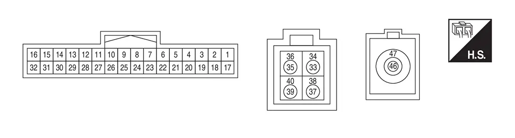
With ProPILOT Assist 2.1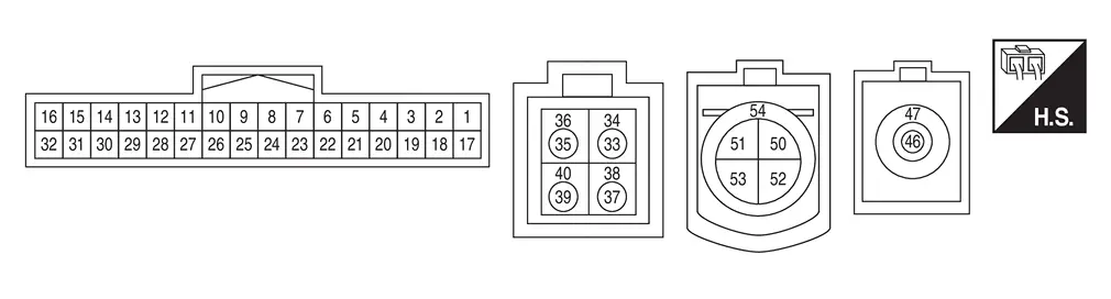
PHYSICAL VALUES
|
Terminal (Wire color) | Description | Condition |
Reference value (Approx.) | ||
|---|---|---|---|---|---|
| + | – | Signal name | Input/Output | ||
|
11 (LA/G) |
16 (B) |
ACC power supply | Input | [Ignition switch ACC] | Battery voltage |
|
3 (BR) |
— | CAN-High | Input/Output | — | — |
|
5 (Y) |
— | CAN-Low | Input/Output | — | — |
|
6 (BR) |
— | CAN-High | Input/Output | — | — |
|
7 (L)2 (P)3 |
— | Not used | — | — | — |
|
8 (V) |
— | Not used | — | — | — |
|
131 (LG) |
— | CAN-Low | Input/Output | — | — |
|
15 (G)2 (W)3 |
— | Not used | — | — | — |
|
16 (B) |
Ground | Ground | — | [Ignition switch ON] | 0 V |
|
17 (LA/G) |
16 (B) |
ACC power supply | Input | [Ignition switch ACC] | Battery voltage |
|
20 (P) |
— | CAN-Low | Input/Output | — | — |
|
21 (BR) |
— | CAN-High | Input/Output | — | — |
|
23 (W) |
— | CAN-Low | Input/Output | — | — |
|
24 (SB) |
— | Not used | — | — | — |
|
301 (BR) |
— | CAN-High | Input/Output | — | — |
|
311 (B) |
Ground | Ground | — | [Ignition switch ON] | 0 V |
|
32 (B) |
— | Not used | — | — | — |
|
33 (B) |
34 (Shield) |
LVDS (Side camera LH) | Input/Output | — | — |
|
35 (B) |
36 (Shield) |
LVDS (Side camera RH) | Input/Output | — | — |
|
37 (B) |
38 (Shield) |
LVDS (Rear camera) | Input/Output | — | — |
|
39 (B) |
40 (Shield) |
LVDS (Front camera) | Input/Output | — | — |
|
521 (G) |
— | Ethernet - | Input/Output | — | — |
|
531 (Y) |
— | Ethernet + | Input/Output | — | — |
|
541 (Shield) |
— | Ethernet shield | — | — | — |
|
46 (B) |
47 (Shield) |
Digital video signal (+) | Input/Output | — | — |
|
47 (Shield) |
— | Digital video signal Shield | — | — | — |
1: With ProPILOT Assist 2.1
2: USA production
3: Japan production
Fail-safe
|
DTC Display contents of CONSULT | Fail-safe condition | ||
|---|---|---|---|
| B2A00-52 : Left camera | — | ||
| B2A01-52 : Right camera | — | ||
| B2A02-52 : Rear camera | — | ||
| B2A03-52 : Front camera | — | ||
| B2A04-51 : Around view monitor control unit |
|
||
| B2A05-44 : Around view monitor control unit |
|
||
| B2A05-45 : Around view monitor control unit | |||
| B2A05-46 : Around view monitor control unit | |||
| B2A05-49 : Around view monitor control unit | |||
| B2A05-55 : Around view monitor control unit |
|
||
| B2A1B-31 : Side camera right | Camera image not displayed | ||
| B2A1C-31 : Front camera | |||
| B2A1D-31 : Side camera left | |||
| B2A1F-16 : Camera power supply | |||
| B2A2C-A2 : Power supply | |||
| B2A2C-A3 : Power supply | |||
| B2A2E-51 : Programing error |
|
||
| C21F0-46 : Variant code error |
The following systems are canceled.
*1: ProPILOT Assist 2.1 display is green *2: ProPILOT Assist 2.1 display is blue |
||
| C21F1-72 : Stop lamp relay |
The following systems are canceled.
*1: ProPILOT Assist 2.1 display is green *2: ProPILOT Assist 2.1 display is blue |
||
| C21F2-04 : ABS actuator and electric unit |
The following systems are canceled.
*1: ProPILOT Assist 2.1 display is green *2: ProPILOT Assist 2.1 display is blue |
||
| C21F6-49 : Camera |
The following systems are canceled.
*1: ProPILOT Assist 2.1 display is green *2: ProPILOT Assist 2.1 display is blue |
||
| C21F6-54 : Camera |
The following systems are canceled.
*1: ProPILOT Assist 2.1 display is green *2: ProPILOT Assist 2.1 display is blue |
||
| C21F6-98 : Camera |
The following systems are canceled.
*1: ProPILOT Assist 2.1 display is green *2: ProPILOT Assist 2.1 display is blue |
||
| C21F7-62 : Electric parking brake system | — | ||
| C21F8-04 : Steering angle sensor |
The following systems are canceled.
*1: ProPILOT Assist 2.1 display is green *2: ProPILOT Assist 2.1 display is blue |
||
| C21F8-62 : Steering angle sensor |
The following systems are canceled.
*1: ProPILOT Assist 2.1 display is green *2: ProPILOT Assist 2.1 display is blue |
||
| C21F8-64 : Steering angle sensor |
The following systems are canceled.
*1: ProPILOT Assist 2.1 display is green *2: ProPILOT Assist 2.1 display is blue |
||
| C21F9-64 : Nissan Ariya Vehicle speed sensor |
The following systems are canceled.
*1: ProPILOT Assist 2.1 display is green *2: ProPILOT Assist 2.1 display is blue |
||
| C21FA-A2 : Power supply circuit |
The following systems are canceled.
*1: ProPILOT Assist 2.1 display is green *2: ProPILOT Assist 2.1 display is blue |
||
| C21FA-A3 : Power supply circuit |
The following systems are canceled.
*1: ProPILOT Assist 2.1 display is green *2: ProPILOT Assist 2.1 display is blue |
||
| C21FB-64 : Chassis control module | — | ||
| C21FC-78 : GEAR POSITION | |||
| C21FE-76 : NP RANGE | |||
| U1327-52 : MAC key update | |||
| U1327-54 : MAC key update | |||
| U1D98-86 : Nissan Ariya Vehicle speed sensor |
The following systems are canceled.
*1: ProPILOT Assist 2.1 display is green *2: ProPILOT Assist 2.1 display is blue |
||
| U1D99-82 : ADAS control unit |
The following systems are canceled.
|
||
| U1D9A-82 : ADAS control unit |
The following systems are canceled.
|
||
| U1D9A-83 : ADAS control unit |
The following systems are canceled.
|
||
| U1D9B-82 : ADAS control unit |
The following systems are canceled.
|
||
| U1D9B-83 : ADAS control unit |
The following systems are canceled.
|
||
| U1D9C-82 : Side radar rear RH | — | ||
| U1D9D-82 : TCM |
The following systems are canceled.
*1: ProPILOT Assist 2.1 display is green *2: ProPILOT Assist 2.1 display is blue |
||
| U1D9D-83 : TCM |
The following systems are canceled.
*1: ProPILOT Assist 2.1 display is green *2: ProPILOT Assist 2.1 display is blue |
||
| U1D9E-82 : ADAS control unit |
The following systems are canceled.
|
||
| U1D9E-83 : ADAS control unit |
The following systems are canceled.
|
||
| U1D9E-87 : ADAS control unit |
The following systems are canceled.
|
||
| U1DA1-82 : BCM |
The following systems are canceled.
*1: ProPILOT Assist 2.1 display is green *2: ProPILOT Assist 2.1 display is blue |
||
| U1DA1-83 : BCM |
The following systems are canceled.
*1: ProPILOT Assist 2.1 display is green *2: ProPILOT Assist 2.1 display is blue |
||
| U1DA2-82 : ECM |
The following systems are canceled.
*1: ProPILOT Assist 2.1 display is green *2: ProPILOT Assist 2.1 display is blue |
||
| U1DA2-83 : ECM |
The following systems are canceled.
*1: ProPILOT Assist 2.1 display is green *2: ProPILOT Assist 2.1 display is blue |
||
| U1DA3-82 : EPS control unit |
The following systems are canceled.
*1: ProPILOT Assist 2.1 display is green *2: ProPILOT Assist 2.1 display is blue |
||
| U1DA4-82 : Head up display unit |
The following systems are canceled.
|
||
| U1DA4-83 : Head up display unit |
The following systems are canceled.
|
||
| U1DA5-82 : Chassis control module |
The following systems are canceled.
*1: ProPILOT Assist 2.1 display is green *2: ProPILOT Assist 2.1 display is blue |
||
| U1DA7-82 : ABS actuator and electric unit |
The following systems are canceled.
*1: ProPILOT Assist 2.1 display is green *2: ProPILOT Assist 2.1 display is blue |
||
| U1DA7-83 : ABS actuator and electric unit |
The following systems are canceled.
*1: ProPILOT Assist 2.1 display is green *2: ProPILOT Assist 2.1 display is blue |
||
| U1DA8-82 : Steering angle sensor |
The following systems are canceled.
*1: ProPILOT Assist 2.1 display is green *2: ProPILOT Assist 2.1 display is blue |
||
| U1DA8-83 : Steering angle sensor |
The following systems are canceled.
*1: ProPILOT Assist 2.1 display is green *2: ProPILOT Assist 2.1 display is blue |
||
| U1DAA-82 : Air bag diagnosis sensor unit | — | ||
| U1DAA-83 : Air bag diagnosis sensor unit | — | ||
| U1DAC-82 : Combination meter |
The following systems are canceled.
*1: ProPILOT Assist 2.1 display is green *2: ProPILOT Assist 2.1 display is blue |
||
| U1DAC-83 : Combination meter |
The following systems are canceled.
*1: ProPILOT Assist 2.1 display is green *2: ProPILOT Assist 2.1 display is blue |
||
| U1DAE-82 : Sonar control unit |
The following systems are canceled.
|
||
| U1DAE-83 : Sonar control unit |
The following systems are canceled.
|
||
| U1DB1-82 : Side radar rear LH |
The following systems are canceled.
|
||
| U1DB1-83 : Side radar rear LH |
The following systems are canceled.
|
||
| U1DB2-82 : Side radar rear RH | — | ||
| U1DB2-83 : Side radar rear RH |
The following systems are canceled.
|
||
| U1DB3-82 : IPDM E/R |
The following systems are canceled.
|
||
| U1DB3-83 : IPDM E/R |
The following systems are canceled.
|
||
| U1DB4-82 : Front camera unit |
The following systems are canceled.
*1: ProPILOT Assist 2.1 display is green *2: ProPILOT Assist 2.1 display is blue |
||
| U1DB4-83 : Front camera unit |
The following systems are canceled.
*1: ProPILOT Assist 2.1 display is green *2: ProPILOT Assist 2.1 display is blue |
||
| U1DB4-87 : Front camera unit |
The following systems are canceled.
*1: ProPILOT Assist 2.1 display is green *2: ProPILOT Assist 2.1 display is blue |
||
| U1DB5-82 : Chassis control module |
The following systems are canceled.
*1: ProPILOT Assist 2.1 display is green *2: ProPILOT Assist 2.1 display is blue |
||
| U1DB5-83 : Chassis control module |
The following systems are canceled.
*1: ProPILOT Assist 2.1 display is green *2: ProPILOT Assist 2.1 display is blue |
||
| U1DB6-82 : Chassis control module |
The following systems are canceled.
*1: ProPILOT Assist 2.1 display is green *2: ProPILOT Assist 2.1 display is blue |
||
| U1DB6-83 : Chassis control module |
The following systems are canceled.
*1: ProPILOT Assist 2.1 display is green *2: ProPILOT Assist 2.1 display is blue |
||
| U1DB7-82 : EPS C/U |
The following systems are canceled.
*1: ProPILOT Assist 2.1 display is green *2: ProPILOT Assist 2.1 display is blue |
||
| U1DB7-83 : EPS C/U |
The following systems are canceled.
*1: ProPILOT Assist 2.1 display is green *2: ProPILOT Assist 2.1 display is blue |
||
| U1DB8-82 : Sonar control unit | — | ||
| U1DB8-83 : Sonar control unit | — | ||
| U1DB9-82 : ABS actuator and electric unit |
The following systems are canceled.
*1: ProPILOT Assist 2.1 display is green *2: ProPILOT Assist 2.1 display is blue |
||
| U1DB9-83 : ABS actuator and electric unit |
The following systems are canceled.
*1: ProPILOT Assist 2.1 display is green *2: ProPILOT Assist 2.1 display is blue |
||
| U1DBA-82 : ABS actuator and electric unit |
The following systems are canceled.
*1: ProPILOT Assist 2.1 display is green *2: ProPILOT Assist 2.1 display is blue |
||
| U1DBA-83 : ABS actuator and electric unit |
The following systems are canceled.
*1: ProPILOT Assist 2.1 display is green *2: ProPILOT Assist 2.1 display is blue |
||
| U1EC4-87: CAN communication error | — | ||
| U1EC5-87: CAN communication error | |||
| U1EC6-87: CAN communication error | |||
| U2140-57 : CAN communication error (ECM) |
The following systems are canceled.
*1: ProPILOT Assist 2.1 display is green *2: ProPILOT Assist 2.1 display is blue |
||
| U2140-87 : CAN communication error (ECM) |
*1: ProPILOT Assist 2.1 display is green *2: ProPILOT Assist 2.1 display is blue |
||
| U2141-87 : CAN communication error (TCM) |
*1: ProPILOT Assist 2.1 display is green *2: ProPILOT Assist 2.1 display is blue |
||
| U2148-87 : CAN communication error [ABS actuator and electric unit (control unit)] |
*1: ProPILOT Assist 2.1 display is green *2: ProPILOT Assist 2.1 display is blue |
||
| U214E-87 : CAN communication error (combination meter) |
The following systems are canceled.
*1: ProPILOT Assist 2.1 display is green *2: ProPILOT Assist 2.1 display is blue |
||
| U214F-57 : CAN communication error (BCM) |
*1: ProPILOT Assist 2.1 display is green *2: ProPILOT Assist 2.1 display is blue |
||
| U214F-87: CAN communication error (BCM) |
|
||
| U2152-57: CAN communication error (ADAS control unit) | — | ||
| U2152-87: CAN communication error (ADAS control unit) | — | ||
| U2154-87: CAN communication error (AV control unit) |
|
||
| U2156-87: CAN comm err (steering angle sensor) |
The following systems are canceled.
*1: ProPILOT Assist 2.1 display is green *2: ProPILOT Assist 2.1 display is blue |
||
| U215B-87 : CAN communication error (IPDM E/R) |
|
||
| U2165-57 : CAN communication error (sonar control unit) |
The following systems are canceled.
*1: ProPILOT Assist 2.1 display is green *2: ProPILOT Assist 2.1 display is blue |
||
| U2165-87: CAN communication error (sonar control unit) |
|
||
| U2176-57 : CAN communication error (chassis control module) |
*1: ProPILOT Assist 2.1 display is green *2: ProPILOT Assist 2.1 display is blue |
||
| U2248-87 : CAN communication error [ABS actuator and electric unit (control unit)] |
The following systems are canceled.
*1: ProPILOT Assist 2.1 display is green *2: ProPILOT Assist 2.1 display is blue |
||
| U2259-87 : CAN communication error (steering unit) |
The following systems are canceled.
*1: ProPILOT Assist 2.1 display is green *2: ProPILOT Assist 2.1 display is blue |
||
| U2265-87 : CAN communication error (sonar control unit) | — | ||
| U2273-87 : CAN communication error (Head Up Display unit) | — | ||
| U2276-87 : CAN communication error (chassis control module) |
The following systems are canceled.
*1: ProPILOT Assist 2.1 display is green *2: ProPILOT Assist 2.1 display is blue |
||
| U2348-87 : CAN communication error [ABS actuator and electric unit (control unit)] |
The following systems are canceled.
*1: ProPILOT Assist 2.1 display is green *2: ProPILOT Assist 2.1 display is blue |
||
| U234F-57 : CAN communication error (BCM) |
The following systems are canceled.
*1: ProPILOT Assist 2.1 display is green *2: ProPILOT Assist 2.1 display is blue |
||
| U2350-87 : CAN communication error (air bag diagnosis sensor unit) | — | ||
| U2354-87 : CAN communication error (AV control unit) |
|
||
| U236E-87 : CAN communication error (side radar) | — | ||
| U2376-57 : CAN communication error (chassis control module) |
The following systems are canceled.
*1: ProPILOT Assist 2.1 display is green *2: ProPILOT Assist 2.1 display is blue |
||
| U2376-87 : CAN communication error (chassis control module) |
The following systems are canceled.
*1: ProPILOT Assist 2.1 display is green *2: ProPILOT Assist 2.1 display is blue |
||
| U2452-87 : CAN communication error (ADAS control unit) |
The following systems are canceled.
|
||
| U246C-87 : CAN communication error (side radar) | — | ||
| U246E-87 : CAN communication error (side radar) | |||
| U2775-88 : Ethernet circuit | |||
| U2A0A-88: Communication Bus Off ITS6-FD | |||
DTC Inspection Priority Chart
If multiple DTCs are detected simultaneously, check them one by one depending on the following DTC inspection priority chart.
| Priority | Detected items (DTC) |
|---|---|
| 1 |
B2A2C-A2: Power supply B2A2C-A3: Power supply |
| 2 | U1327-54: MAC key update |
| 3 | U1327-52: MAC key update |
| 4 | B2A05-55: Around view monitor control unit |
| 5 |
U1D9E-87: ADAS control unit U1DB4-87: Front camera unit U1EC4-87:CAN communication error U1EC5-87:CAN communication error U1EC6-87:CAN communication error U2140-87: CAN communication error (ECM) U2141-87: CAN communication error (TCM) U2148-87: CAN communication error [ABS actuator and electric unit (control unit)] U214E-87: CAN communication error (combination meter) U214F-87: CAN communication error (BCM) U2152-87: CAN communication error (ADAS control unit) U2154-87: CAN communication error (AV control unit) U2156-87: CAN communication error (steering angel sensor) U215B-87: CAN communication error (IPDM E/R) U2165-87: CAN communication error (sonar control unit) U2248-87: CAN communication error [ABS actuator and electric unit (control unit)] U2259-87: CAN communication error (steering control unit) U2265-87: CAN communication error (sonar control unit) U2273-87: CAN communication error (Head Up Display unit) U2276-87: CAN communication error (chassis control module) U2348-87: CAN communication error [ABS actuator and electric unit (control unit)] U2350-87: CAN communication error (air bag diagnosis sensor unit) U2354-87: CAN communication error (AV control unit) U236E-87: CAN communication error (side radar) U2376-87: CAN communication error (chassis control module) U2452-87: CAN communication error (ADAS control unit) U246C-87: CAN communication error (side radar) U246E-87: CAN communication error (side radar) U2775-88: Ethernet circuit U2A0A-88:Communication Bus Off ITS6-FD |
| 6 |
B2A05-44: Around view monitor control unit B2A05-45: Around view monitor control unit B2A05-46: Around view monitor control unit B2A05-49: Around view monitor control unit B2A07-86: Steering angle sensor B2A0A-86: Sonar control unit B2A0B-86: ABS actuator and electric unit B2A0C-86: TCM B2A1A-13: Rear camera B2A1A-31: Rear camera B2A1B-13: Side camera right B2A1B-31: Side camera right B2A1C-13: Front camera B2A1C-31: Front camera B2A1D-13: Side camera left B2A1D-31: Side camera left B2A1F-16: Camera power supply B2A2E-51: Programing error U1D99-82: ADAS control unit U1D9A-82: ADAS control unit U1D9A-83: ADAS control unit U1D9B-82: ADAS control unit U1D9B-83: ADAS control unit U1D9C-82: Side radar rear RH U1D9D-82: TCM U1D9D-83: TCM U1D9E-82: ADAS control unit U1D9E-83: ADAS control unit U1DA1-82: BCM U1DA1-83: BCM U1DA2-82: ECM U1DA2-83: ECM U1DA3-82: EPS control unit U1DA4-82: Head up display unit U1DA4-83: Head up display unit U1DA5-82: Chassis control module U1DA7-82: ABS actuator and electric unit U1DA7-83: ABS actuator and electric unit U1DA8-82: Steering angle sensor U1DA8-83: Steering angle sensor U1DAA-82: Air bag diagnosis sensor unit U1DAA-83: Air bag diagnosis sensor unit U1DAC-82: Combination meter U1DAC-83: Combination meter U1DAE-82: Sonar control unit U1DAE-83: Sonar control unit U1DB1-82: Side radar rear LH U1DB1-83: Side radar rear LH U1DB2-82: Side radar rear RH U1DB2-83: Side radar rear RH U1DB3-82: IPDM E/R U1DB3-83: IPDM E/R U1DB4-82: Front camera unit U1DB4-83: Front camera unit U1DB5-82: Chassis control module U1DB5-83: Chassis control module U1DB6-82: Chassis control module U1DB6-83: Chassis control module U1DB7-82: EPS C/U U1DB7-83: EPS C/U U1DB8-82: Sonar control unit U1DB8-83: Sonar control unit U1DB9-82: ABS actuator and electric unit U1DB9-83: ABS actuator and electric unit U1DBA-82: ABS actuator and electric unit U1DBA-83: ABS actuator and electric unit U2140-57: CAN communication error (ECM) U214F-57: CAN communication error (BCM) U2152-57: CAN communication error (ADAS control unit) U2165-57: CAN communication error (sonar control unit) U2176-57: CAN communication error (chassis control module) U234F-57: CAN communication error (BCM) U2376-57: CAN communication error (chassis control module) |
| 7 |
B2A00-52: Left camera B2A01-52: Right camera B2A02-52: Rear camera B2A03-52: Front camera |
| 8 | B2A04-51: Around view monitor control unit |
| 9 | C21F6-54: Camera |
| 10 |
C21F0-46: Variant code error C21F1-72: Stop lamp relay C21F2-04: ABS actuator and electric unit C21F6-49: Camera C21F6-98: Camera C21F7-62: Electric parking brake system C21F8-04: Steering angle sensor C21F8-62: Steering angle sensor C21F8-64: Steering angle sensor C21F9-64: Nissan Ariya Vehicle speed sensor C21FA-A2: Power supply circuit C21FA-A3: Power supply circuit C21FB-64: Chassis control module C21FC-78: GEAR POSITION C21FE-76: NP RANGE U1D98-86: Nissan Ariya Vehicle speed sensor |
DTC Index
Self diagnostic result
| DTC | CONSULT display | Refer to |
|---|---|---|
| B2A00-52 | Left camera | DTC Description |
| B2A01-52 | Right camera | DTC Description |
| B2A02-52 | Rear camera | DTC Description |
| B2A03-52 | Front camera | DTC Description |
| B2A04-51 | Around view monitor control unit | DTC Description |
| B2A05-44 | Around view monitor control unit | DTC Description |
| B2A05-45 | Around view monitor control unit | DTC Description |
| B2A05-46 | Around view monitor control unit | DTC Description |
| B2A05-49 | Around view monitor control unit | DTC Description |
| B2A05-55 | Around view monitor control unit | DTC Description |
| B2A07-86 | Steering angle sensor | DTC Description |
| B2A0A-86 | Sonar control unit | DTC Description |
| B2A0B-86 | ABS actuator and electric unit | DTC Description |
| B2A0C-86 | TCM | DTC Description |
| B2A1A-13 | Rear camera | DTC Description |
| B2A1A-31 | Rear camera | DTC Description |
| B2A1B-13 | Right camera | DTC Description |
| B2A1B-31 | Right camera | DTC Description |
| B2A1C-13 | Front camera | DTC Description |
| B2A1C-31 | Front camera | DTC Description |
| B2A1D-13 | Left camera | DTC Description |
| B2A1D-31 | Left camera | DTC Description |
| B2A1F-16 | Camera power supply | DTC Description |
| B2A2C-A2 | Power supply | DTC Description |
| B2A2C-A3 | Power supply | DTC Description |
| B2A2E-51 | Programing error | DTC Description |
| C21F0–46 | Variant code error | DTC Description |
| C21F1-72 | Stop lamp relay | DTC Description |
| C21F2-04 | ABS actuator and electric unit | DTC Description |
| C21F6-49 | Camera | DTC Description |
| C21F6-54 | Camera | DTC Description |
| C21F6-98 | Camera | DTC Description |
| C21F7-62 | Electric parking brake system | DTC Description |
| C21F8-04 | Steering angle sensor | DTC Description |
| C21F8-62 | Steering angle sensor | DTC Description |
| C21F8-64 | Steering angle sensor | DTC Description |
| C21F9-64 | Nissan Ariya Vehicle speed sensor | DTC Description |
| C21FA-A2 | Power supply circuit | DTC Description |
| C21FA-A3 | Power supply circuit | DTC Description |
| C21FB-64 | Chassis control module | DTC Description |
| C21FC-78 | GEAR POSITION | DTC Description |
| C21FE-76 | NP RANGE | DTC Description |
Network-DTC
| DTC | CONSULT display | Refer to |
|---|---|---|
| U1D98-86 | Nissan Ariya Vehicle speed sensor | DTC Description |
| U1D99-82 | ADAS control unit | DTC Description |
| U1D9A-82 | ADAS control unit | DTC Description |
| U1D9A-83 | ADAS control unit | DTC Description |
| U1D9B-82 | ADAS control unit | DTC Description |
| U1D9B-83 | ADAS control unit | DTC Description |
| U1D9C-82 | Side radar rear RH | DTC Description |
| U1D9D-82 | TCM | DTC Description |
| U1D9D-83 | TCM | DTC Description |
| U1D9E-82 | ADAS control unit | DTC Description |
| U1D9E-83 | ADAS control unit | DTC Description |
| U1DA1-82 | BCM | DTC Description |
| U1DA1-83 | BCM | DTC Description |
| U1DA2-82 | ECM | DTC Description |
| U1DA2-83 | ECM | DTC Description |
| U1DA3-82 | EPS control unit | DTC Description |
| U1DA4-82 | Head UP Display unit | DTC Description |
| U1DA4-83 | Head UP Display unit | DTC Description |
| U1DA5-82 | Chassis control module | DTC Description |
| U1DA7-82 | ABS actuator and electric unit | DTC Description |
| U1DA7-83 | ABS actuator and electric unit | DTC Description |
| U1DA8-82 | Steering angle sensor | DTC Description |
| U1DA8-83 | Steering angle sensor | DTC Description |
| U1DAA-82 | Air bag diagnosis sensor unit | DTC Description |
| U1DAA-83 | Air bag diagnosis sensor unit | DTC Description |
| U1DAC-82 | Combination meter | DTC Description |
| U1DAC-83 | Combination meter | DTC Description |
| U1DAE-82 | Sonar control unit | DTC Description |
| U1DAE-83 | Sonar control unit | DTC Description |
| U1DB1-82 | Side radar rear LH | DTC Description |
| U1DB1-83 | Side radar rear LH | DTC Description |
| U1DB2-82 | Side radar rear RH | DTC Description |
| U1DB2-83 | Side radar rear RH | DTC Description |
| U1DB3-82 | IPDM E/R | DTC Description |
| U1DB3-83 | IPDM E/R | DTC Description |
| U1DB4-82 | Front camera unit | DTC Description |
| U1DB4-83 | Front camera unit | DTC Description |
| U1DB4-87 | Front camera unit | DTC Description |
| U1DB5-82 | Chassis control module | DTC Description |
| U1DB5-83 | Chassis control module | DTC Description |
| U1DB6-82 | Chassis control module | DTC Description |
| U1DB6-83 | Chassis control module | DTC Description |
| U1DB7-82 | EPS C/U | DTC Description |
| U1DB7-83 | EPS C/U | DTC Description |
| U1DB8-82 | Sonar control unit | DTC Description |
| U1DB8-83 | Sonar control unit | DTC Description |
| U1DB9-82 | ABS actuator and electric unit | DTC Description |
| U1DB9-83 | ABS actuator and electric unit | DTC Description |
| U1DBA-82 | ABS actuator and electric unit | DTC Description |
| U1DBA-83 | ABS actuator and electric unit | DTC Description |
| U1EC4-87 | CAN communication error | DTC Description |
| U1EC5-87 | CAN communication error | DTC Description |
| U1EC6-87 | CAN communication error | DTC Description |
| U2140-87 | CAN communication error (ECM) | DTC Description |
| U2141-87 | CAN comm err (TCM) | DTC Description |
| U2148-87 | CAN comm err (brake control unit) | DTC Description |
| U214E-87 | CAN comm err (combination meter) | DTC Description |
| U214F-87 | CAN comm err (BCM) | DTC Description |
| U2152-87 | CAN comm err (ADAS control unit) | DTC Description |
| U2154-87 | CAN comm err (MIU) | DTC Description |
| U2156-87 | CAN comm err (steering angel sensor) | DTC Description |
| U215B-87 | CAN comm err (IPDM E/R) | DTC Description |
| U2165-87 | CAN comm err (sonar) | DTC Description |
| U2248-87 | CAN communication error [ABS actuator and electric unit (control unit)] | DTC Description |
| U2259-87 | CAN communication error (steering unit) | DTC Description |
| U2265-87 | CAN comm err (sonar) | DTC Description |
| U2273-87 | CAN communication error (Head Up Display unit) | DTC Description |
| U2276-87 | CAN communication error (chassis control module) | DTC Description |
| U2348-87 | CAN communication error [ABS actuator and electric unit (control unit)] | DTC Description |
| U2350-87 | CAN communication error (air bag diagnosis sensor unit) | DTC Description |
| U2354-87 | CAN comm err (MIU) | DTC Description |
| U236E-87 | CAN comm err (side radar) | DTC Description |
| U2376-87 | CAN communication error (chassis control module) | DTC Description |
| U2452-87 | CAN communication error (ADAS control unit) | DTC Description |
| U246C-87 | CAN communication error (side radar) | DTC Description |
| U246E-87 | CAN communication error (side radar) | DTC Description |
| U2775-88 | Ethernet circuit | DTC Description |
| U2A04-88 | Comm Bus Off ITS1-FD | DTC Description |
| U2A05-88 | Comm Bus Off ITS4-FD | DTC Description |
| U2A08-88 | Comm Bus Off ITS3-FD | DTC Description |
| U2A0A-88 | Communication Bus Off ITS6-FD | DTC Description |
MAC Diagnosis
| DTC | CONSULT display | Refer to |
|---|---|---|
| U1327-52 | MAC Key update | DTC Description |
| U1327-54 | MAC Key update | DTC Description |
| U2140-57 | CAN communication error (ECM) | DTC Description |
| U214F-57 | CAN comm err (BCM) | DTC Description |
| U2152-57 | CAN comm err (ADAS control unit) | DTC Description |
| U2165-57 | CAN communication error (sonar control unit) | DTC Description |
| U2176-57 | CAN comm err (CCM) | DTC Description |
| U234F-57 | CAN communication error(BCM) | DTC Description |
| U2376-57 | CAN communication error (chassis control module) | DTC Description |
Other materials:
Brake assist
Brake assist
When brake pedal force exceeds a certain
threshold, Brake Assist activates to provide
greater braking force than a conventional
brake booster, even with relatively light pedal
pressure.
WARNING
Brake Assist supports braking but does
not replace careful driving. It is not a collision
wa ...
For Side and Rollover Collision
When SRS is activated in a collision
FOR SIDE AND ROLLOVER COLLISION: When SRS is activated in a collisionCAUTION:
Due to varying models and option levels, not all parts listed in the chart below apply to all Nissan Ariya vehicles.
WORK PROCEDURE
Before performing any of the following steps, e ...
Dtc/circuit Diagnosis. Front Washer Circuit
Component Function Check
CHECK FRONT WASHER OPERATION
When the front washer switch is turned to the ON position the front washer should operate.
Is front washer operation normal?
YES>>
Washer switch circuit is normal.
NO>>
Refer to Diagnosis Procedure.
Diagnosis Procedure
COMB ...