Nissan Rogue (T33) 2021-Present Service Manual: Ignition Relay-3
Diagnosis Procedure
CHECK IGNITION RELAY-3 POWER SUPPLY
-
Disconnect ignition relay-3 connector.
-
Check voltage between ignition relay-3 harness connector and ground.
(+) (–) Voltage
(Approx.)Ignition relay-3 Connector Terminal E83 1 Ground Battery voltage 4
Is the inspection result normal?
YES>>GO TO 2.
NO>>Repair or replace harness or connectors.
CHECK IGNITION RELAY-3
Check ignition relay-3. Refer to Component Inspection.
Is the inspection result normal?
YES>>GO TO 3.
NO>>Replace ignition relay-3.
CHECK IGNITION RELAY-3 CONTROL SIGNAL CIRCUIT
-
Disconnect BCM connector.
-
Check continuity between BCM harness connector and ignition relay-3 harness connector.
With type A meter BCM Ignition relay-3 Continuity Connector Terminal Connector Terminal M51 33 E83 2 Yes With type B meter BCM Ignition relay-3 Continuity Connector Terminal Connector Terminal M18 40 E83 2 Yes -
Check continuity between BCM harness connector and ground.
With type A meter BCM — Continuity Connector Terminal M51 33 Ground No With type A meter BCM — Continuity Connector Terminal M18 40 Ground No
Is the inspection result normal?
YES>>Replace BCM. Refer to Removal and Installation.
NO>>Repair or replace harness or connectors.
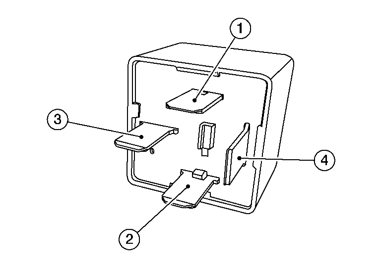
Component Inspection
CHECK IGNITION RELAY-3
-
Ignition switch OFF.
-
Disconnect ignition relay-3 connector.
-
Check continuity between ignition relay-3 terminals.
| Ignition relay-3 | Condition | Continuity | |
|---|---|---|---|
| Terminals | |||
| 3 | 4 | 12 V direct current supply between terminals 1 and 2. | Yes |
| No current supply | No | ||
Is the inspection result normal?
YES>>Inspection End.
NO>>Replace ignition relay-3.
Other materials:
Dtc/circuit Diagnosis. C18d6-09 Brake Power Supply Back up Unit
DTC Description
DTC DETECTION LOGIC DTC No. CONSULT screen terms DTC detection condition
C18D6
09
Backup power supply unit
1
Diagnosis condition
When Ignition switch is ON.
Signal (terminal)
Brake power supply backup unit signal
Threshold
When a malfunction is de ...
C10b1-01 Parking Brake Actuator (lh)
DTC Description
DTC DETECTION LOGIC DTC No.
CONSULT screen terms
(Trouble diagnosis content) DTC detection condition
C10B1
01
Parking brake actuator (LH)
[Parking brake actuator (left)]
Diagnosis condition
When parking brake is apply or release
Signal (terminal)
—
...
Removal and Installation. Tire Pressure Sensor
Exploded View
Screw
Tire pressure sensor
Valve
Valve core
Valve cap
: Comply with the assembly procedure when tightening. Refer to Removal and Installation.
: N·m (kg-m, in-lb)
: Always replace after every disassembly.
Removal & Install ...