Nissan Rogue Service Manual: Fender protector
FENDER PROTECTOR
FENDER PROTECTOR : Exploded View
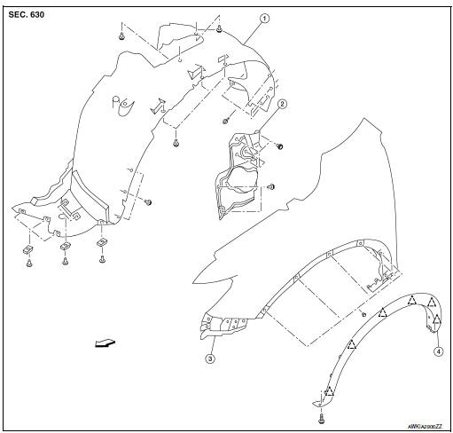
- Front fender protector
- Engine side cover
- Front fender
- Over fender
 Clip
Clip
 Front
Front
FENDER PROTECTOR : Removal and Installation
REMOVAL
- Remove wheel and tire using power tool. Refer to WT-60, "Removal and Installation".
- Remove front over fender molding. Refer to EXT-30, "FRONT OVER FENDER : Removal and Installation".
- Remove front under cover. Refer to EXT-16, "Exploded View".
- Remove sill molding screw. Refer to EXT-35, "Exploded View - Center Mudguard".
- Remove engine side cover.
- Release front fender protector clips and remove front fender protector.
INSTALLATION
Installation is in the reverse order of removal.
REAR WHEEL HOUSE PROTECTOR
REAR WHEEL HOUSE PROTECTOR : Exploded View
- Rear fender
- Rear wheel house protector
- rear over fender molding
Clip
Front
REAR WHEEL HOUSE PROTECTOR : Removal and Installation
REMOVAL
- Remove rear wheel house protector clip and screws.
- Remove rear wheel house protector nuts and rear wheel house protector.
INSTALLATION
Installation is in the reverse order of removal.
 Cowl top
Exploded View
Cowl top side trim cover (RH)
Cowl top cover screen
Cowl top cover seal
EPT seal
Cowl top cover plug
Cowl top cover
Cowl top cover mask
Cowl top ex ...
 Over fender
FRONT OVER FENDER
FRONT OVER FENDER : Exploded View
Front fender protector
Front fender
Front over fender molding
Clip
FRONT OVER FENDER : Removal and Installation
REM ...
Other materials:
C1115 ABS sensor [abnormal signal]
DTC Logic
DTC DETECTION LOGIC
DTC
Display Item
Malfunction detected condition
Possible causes
C1115
ABS SENSOR
[ABNORMAL SIGNAL]
When difference in wheel speed between any wheel
and others is detected while the vehicle is driven because
of installation of ti ...
ID registration cannot be completed
Description
The ID of the tire pressure sensor installed in each wheel cannot be
registered in the tire pressure monitoring
system. Inspect the tire pressure sensor or the tire pressure monitoring system
circuit.
Diagnosis Procedure
1.CHECK TIRE PRESSURE SENSOR ACTIVATION TOOL
Check tire pr ...
The meter control switch is inoperative
Description
The meter control switches are inoperative when pressed.
Diagnosis Procedure
1.CHECK METER CONTROL SWITCH SIGNAL
Check the meter control switch signal. Refer to MWI-67, "Diagnosis
Procedure".
Is the inspection result normal?
YES >> GO TO 2.
NO >> Repair ...
