Nissan Rogue Service Manual: Cowl top
Exploded View
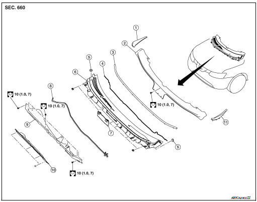
- Cowl top side trim cover (RH)
- Cowl top cover screen
- Cowl top cover seal
- EPT seal
- Cowl top cover plug
- Cowl top cover
- Cowl top cover mask
- Cowl top extension seal
- Cowl top extension
- Cowl top insulation
- Cowl top side trim cover (LH)
Removal and Installation
COWL TOP COVER
Removal
- Remove front wiper arms (LH/RH). Refer to WW-63, "Removal and Installation".
- Release pawls using suitable tool (A) and remove cowl top side
trim cover (1) (LH/RH).
 : Pawl

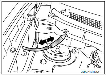
- Disconnect front washer tube connector.
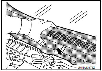
- Remove cowl top cover clips, then pull forward to release cowl top cover and remove.
CAUTION: When performing the procedure after removing cowl top cover, cover the lower end of windshield glass with urethane etc.
- Remove the following parts after removing cowl top cover (if necessary).
- Cowl top seal
- Cowl top cover plug
- Washer nozzle, Refer to WW-60, "Removal and Installation - Front Washer Nozzle".
- Washer tube,WW-60, "Removal and Installation - Front Washer Nozzle".
- EPT sealer
Installation
Installation is in the reverse order of removal.
CAUTION: When installing cowl top cover, check that clips are securely fitted in body panel holes and then press them in.
COWL TOP EXTENSION
Removal
- Remove the front wiper drive assembly. Refer to WW-66, "Removal and Installation".
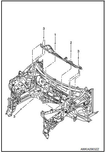
- Remove the cowl top extension bolts and the cowl top extension.
INSTALLATION
Installation is in the reverse order of removal.
CAUTION: When installing cowl top cover, check that clips are securely placed in panel holes on body and then pressed in.
NOTE: When installing the cowl top extension, tighten the bolts to specification in the order shown.
 Front grille
Exploded View
Front bumper fascia
Front camera (if equipped)
Front grille
Front emblem
Pawl
Clip
Removal and Installation
REMOVAL
Remove front grille upper clip (A) ...
 Fender protector
FENDER PROTECTOR
FENDER PROTECTOR : Exploded View
Front fender protector
Engine side cover
Front fender
Over fender
Clip
Front
FENDER PROTECTOR : Removal and Installation
RE ...
Other materials:
Run-flat tires (if so equipped)
Run-flat tires are those tires that can be used
temporarily if they are punctured. For additional
information, refer to “Run-flat tires” in “Maintenance
and do-it-yourself.”
For additional information, refer to the tire safety
information in the Warranty Information Booklet.
WAR ...
Basic inspection
DIAGNOSIS AND REPAIR WORKFLOW
Work Flow
OVERALL SEQUENCE
DETAILED FLOW
1.GET INFORMATION FOR SYMPTOM
Get detailed information from the customer about the symptom (the
condition and the environment when
the incident/malfunction occurs).
Check operation condition of the ...
Diagnosis system (BCM) (without intelligent key system)
COMMON ITEM
COMMON ITEM : CONSULT Function (BCM - COMMON ITEM)
APPLICATION ITEM
CONSULT performs the following functions via CAN communication with BCM.
Direct Diagnostic Mode
Description
Ecu Identification
The BCM part number is displayed.
Self Diagnostic ...
