Nissan Rogue Service Manual: EVAP canister
Exploded View
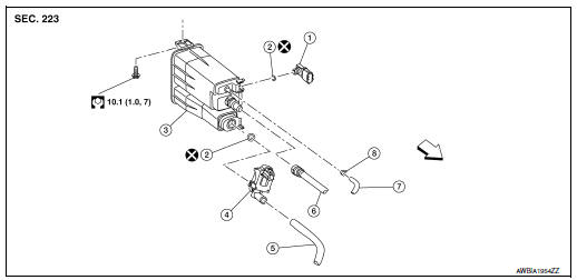
- EVAP control system pressure sensor
- O-ring
- EVAP canister
- EVAP canister vent control valve
- EVAP canister vent control valve hose
- EVAP vent line
- EVAP canister purge hose
- Clamp
 Front
Front
Removal and Installation
NOTE: The EVAP canister vent control valve and EVAP control system pressure sensor can be removed without removing the EVAP canister.
REMOVAL
- Disconnect the EVAP control system pressure sensor harness connector and the EVAP canister vent control valve harness connector.
- Remove EVAP canister filter (1) and place aside (
 ).
).
(2) : EVAP canister
: Front
- Disconnect the EVAP canister purge hose, the EVAP vent line, and the EVAP canister vent control valve hose.
- Remove the EVAP canister bolt.
- Remove the EVAP canister from the vehicle.
- Remove EVAP control system pressure sensor and EVAP canister vent control valve (if necessary).
INSTALLATION Installation is in the reverse order of removal.
Inspection
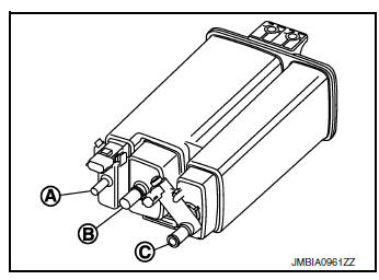
Check EVAP canister as follows:
- Block port (B).
- Blow air into port (A) and check that it flows freely out of port (C).
- Release blocked port (B).
- Apply vacuum pressure to port (B) and check that vacuum pressure exists at the ports (A) and (C).
- Block port (A) and (B).
- Apply pressure to port (C) and check that there is no leakage.
 Fuel tank
FWD
FWD : Exploded View
Fuel filler cap
Grommet
Fuel filler tube
Cover
Clamp
Fuel filler hose
Clamp
Vent hose
Fuel tank p ...
 EVAP canister vent control valve
Exploded View
EVAP control system pressure sensor
O-ring
EVAP canister
EVAP canister vent control valve
EVAP canister vent control valve hose
EVAP vent line
EVAP canister pu ...
Other materials:
Component parts
METER SYSTEM
METER SYSTEM : Component Parts Location
Vehicle front
View of the fuel pump and fuel level
sensor inspection hole covers with
the rear seat removed.
View of front engine assembly
No.
Component
Function
1
Combination me ...
Unit removal and installationEMBER
REAR SUSPENSION M
Exploded View
Rear suspension member
Suspension member stay
(RH)
Suspension member stay (LH)
Bound bumper
Front
Removal and Installation - FWD
REMOVAL
Remove wheel and tires using power tool. Refer to WT-60, "Exploded
Vie ...
FCW system operation
Forward Collision Warning light
The FCW system is active at speeds of approximately
10 MPH (15 km/h) and above, when the
system turns on.
When FCW is turned on, FCW Indicator (white)
will turn on. FCW system is activated using the
settings menu on the information display. For
additional ...
