Nissan Rogue (T33) 2021-Present Service Manual: Entry Assist Function
System Description
SYSTEM DIAGRAM
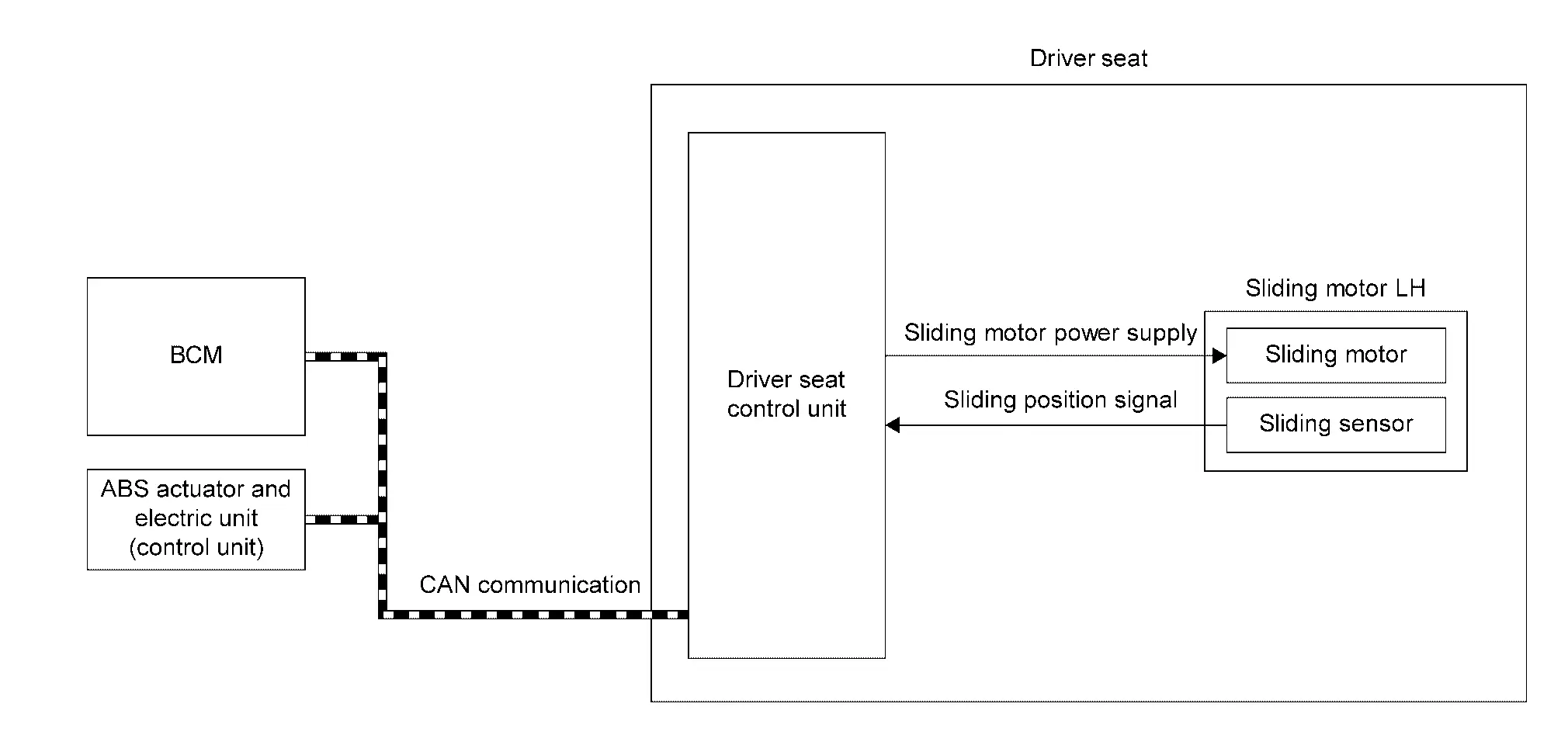
Several types of signals are transmitted from the following units to the driver seat control unit via CAN communication.
| Component | Signal |
|---|---|
| ABS actuator and electric unit (control unit) | Nissan Ariya Vehicle speed signal |
| BCM |
|
| Component | Function | |
|---|---|---|
| Sliding motor LH | Sliding motor |
|
| Sliding sensor |
|
|
| BCM |
Recognizes the following status and transmits it to driver seat control unit via CAN communication:
|
|
| ABS actuator and electric unit (control unit) | ABS actuator and electric unit (control unit) transmits the Nissan Ariya vehicle speed signal to driver seat control unit via CAN communication. | |
| Driver seat control unit | Refer to Driver Seat Control Unit. | |
DESCRIPTION
-
This function allows the driver side seat to return from the exiting position to the position before the exiting function is operated when the ignition switch is operated from OFF to ON when the driver enters the Nissan Ariya vehicle.
-
If the ignition switch is operated with any Intelligent Key other than that used before the exiting function is operated, the driver side seat will return to the driver position registered for that Intelligent Key.
 NOTE:
NOTE:
-
This function is set to ON before delivery (initial setting).
-
Further information for the system setting procedure. Refer to Description.
Operation Condition
-
Ignition switch ON.
-
Driver seat will return from the exiting position to entry position.
Operation Procedure
Satisfy all of the following items. The entry assist function is not performed if these items are not satisfied:
| Item | Status |
|---|---|
| Seat | The Nissan Ariya vehicle is not moved after performing the exit assist function. |
|
Switch inputs
|
OFF (Not operated) |
| Nissan Ariya Vehicle speed | 0 MPH (0 km/h) |
| CONSULT | Not connected |
Detail Flow
| Order | Input | Output | Control unit condition |
|---|---|---|---|
| 1 | Ignition switch | ŌĆö | Driver seat control unit receives the signals of ignition ON signal from BCM via CAN communication. |
| 2 | ŌĆö |
Motors (Sliding) |
Driver seat control unit operates the sliding motor LH when the operating conditions are satisfied. |
| 3 |
Sensors (Sliding) |
ŌĆö | Sliding sensor monitors the operating positions of seat, and then stops the operation of sliding motor LH when seat reaches the recorded positions. |
Other materials:
B2600-42 Configuration Error
DTC Description
DTC DETECTION LOGIC DTC No. CONSULT screen terms DTC detected condition
B2600-42
Configuration error
Diagnosis condition
After the ignition switch OFF, wait for 1 minutes or more
When ignition switch is ON.
Signal (terminal)
ŌĆö
Threshold
...
Combination Meter
Reference Value
VALUES ON THE DIAGNOSIS TOOLNOTE:
The following table includes information (items)
inapplicable to this Nissan Ariya vehicle. For information (items)
applicable to this vehicle, refer to CONSULT display items.
Monitor Item Condition Value/Status
SPEED METER
[mph or km/ ...
Fuel Pump Control Module
Component Inspection
CHECK FUEL PUMP CONTROL MODULE (FPCM)
Check the voltage between FPCM terminals under the following conditions.
FPCM Condition
Voltage
(Approx.)
Connector + ŌłÆ
Terminal
B97
6
5
For 1 second after turning ignition switch ON
9.9 V
More than ...