Nissan Rogue (T33) 2021-Present Service Manual: Electro-Hydraulic Coupling
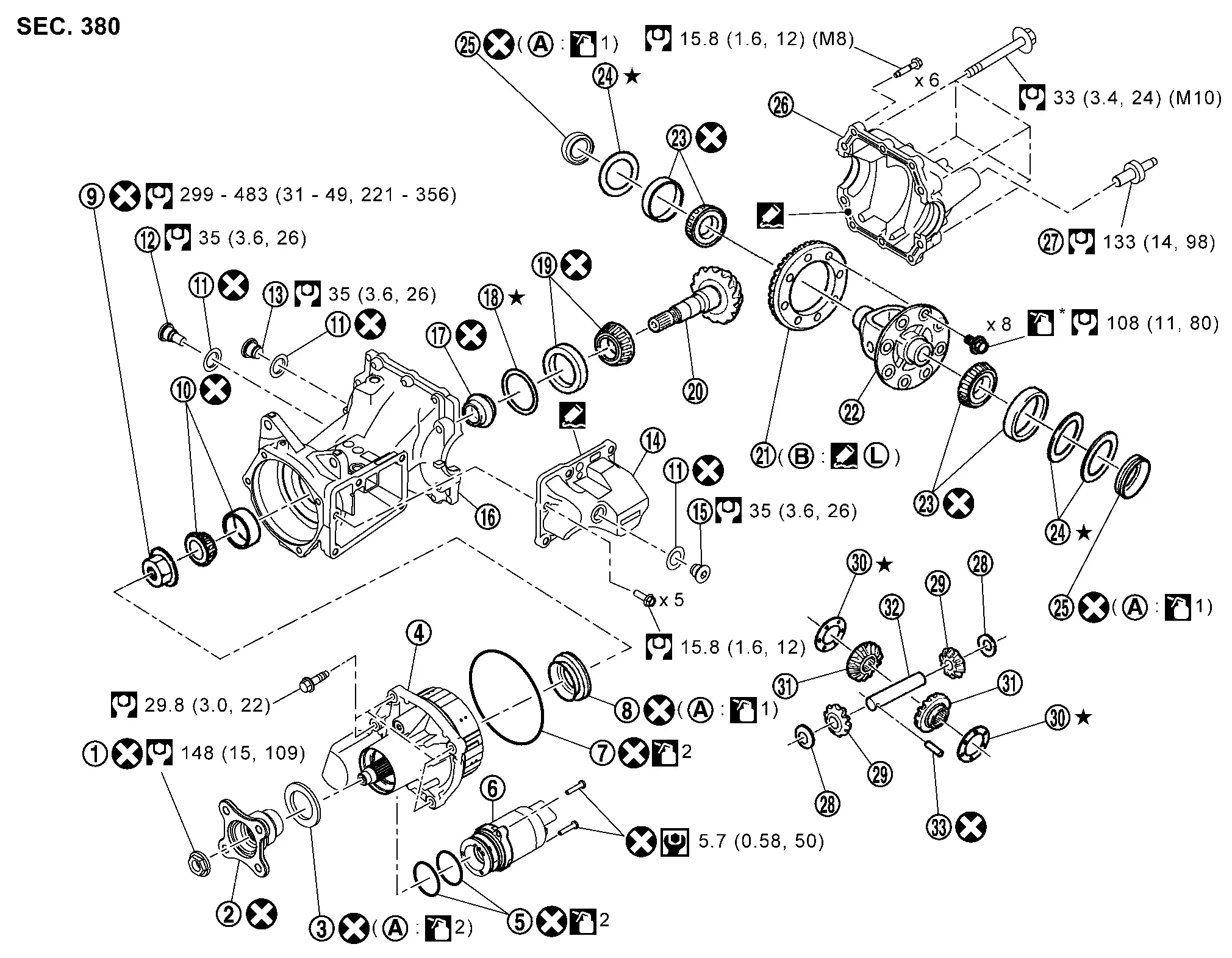
Exploded View
 |
Companion flange lock nut |  |
Companion flange |  |
Electro-hydraulic coupling oil seal |
 |
Electro-hydraulic coupling assembly |  |
O-ring |  |
Actuator assembly |
 |
O-ring |  |
Drive pinion oil seal |  |
Drive pinion lock nut |
 |
Pinion front bearing |  |
Gasket |  |
Drain plug |
 |
Filler plug |  |
Coupling oil tank cover |  |
Filler plug |
 |
Gear carrier |  |
Collapsible spacer |  |
Drive pinion adjusting shim |
 |
Pinion rear bearing |  |
Drive pinion |  |
Drive gear |
 |
Differential case |  |
Side bearing |  |
Side bearing adjusting shim |
 |
Side oil seal |  |
Rear cover |  |
Stud bolt |
 |
Pinion mate thrust washer |  |
Pinion mate gear |  |
Side gear thrust washer |
 |
Side gear |  |
Pinion mate shaft |  |
Lock pin |
 |
Outer circumference |  |
Screw hole | ||
 : N·m (kg-m, in-lb) : N·m (kg-m, in-lb) |
|||||
 : N·m (kg-m, ft-lb) : N·m (kg-m, ft-lb) |
|||||
 : Always replace after every disassembly. : Always replace after every disassembly. |
|||||
 : Select with proper thickness. : Select with proper thickness. |
|||||
 1: Apply gear oil. 1: Apply gear oil. |
|||||
| 2: Apply electro-hydraulic coupling oil (Genuine part). |
|||||
| *: Apply anti-corrosion oil. |
|||||
 : Apply Genuine Silicone RTV or equivalent. Refer to Recommended Chemical Products and Sealants. : Apply Genuine Silicone RTV or equivalent. Refer to Recommended Chemical Products and Sealants. |
|||||
 : Apply Genuine High Strength Thread Locking Sealant or equivalent. Refer to Recommended Chemical Products and Sealants. : Apply Genuine High Strength Thread Locking Sealant or equivalent. Refer to Recommended Chemical Products and Sealants. |
|||||
Disassembly and Assembly
DISASSEMBLY
 NOTE:
NOTE:
Before replacing electro-hydraulic coupling due to vibration and/or noise when making low speed turns, refer to TSB to assist in proper diagnosis.
Remove electro-hydraulic coupling assembly from final drive assembly after removing electro-hydraulic coupling assembly mounting bolts.
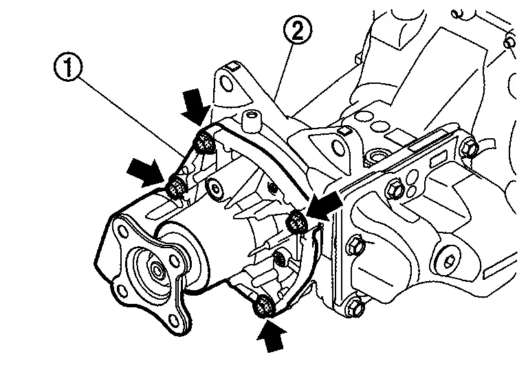
CAUTION:
Oil is drained from between electro-hydraulic coupling assembly and final drive assembly when removing, set a pan under them.
-
If necessary, use cutout
to pry.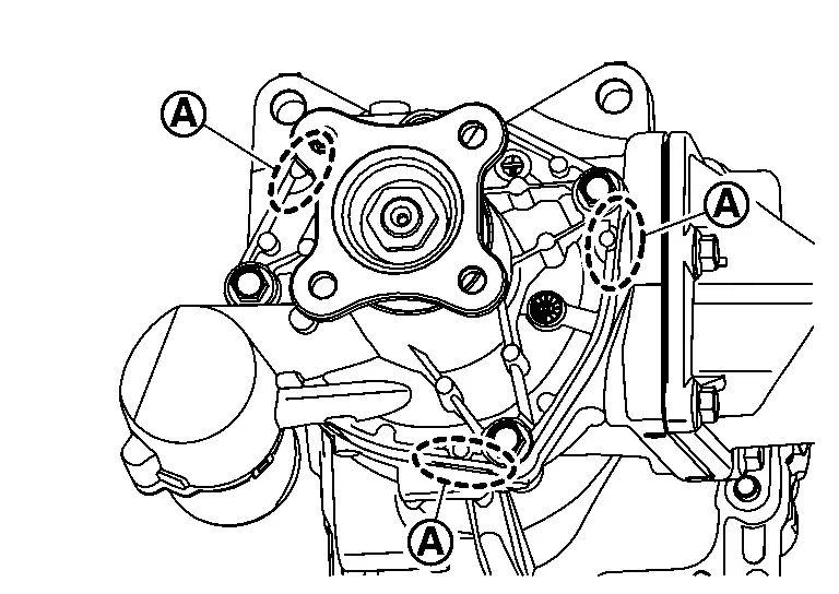
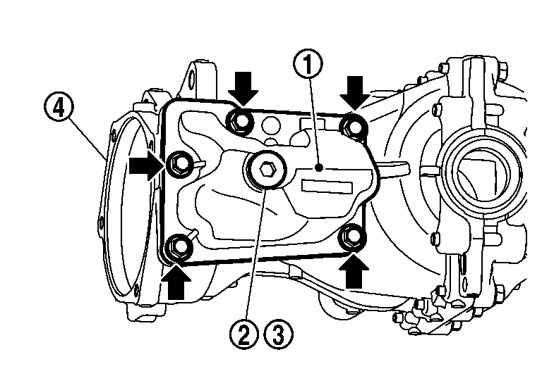
Remove mounting bolts and remove actuator assembly .
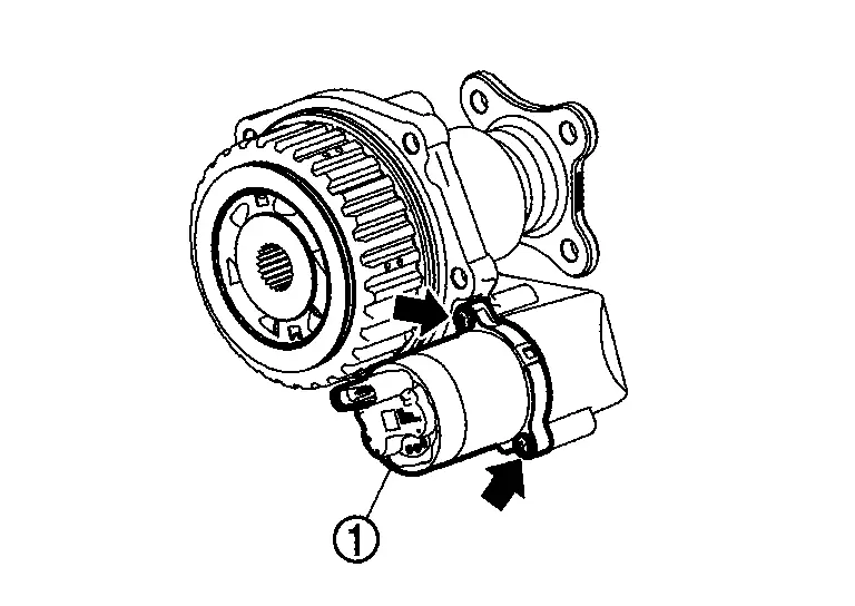
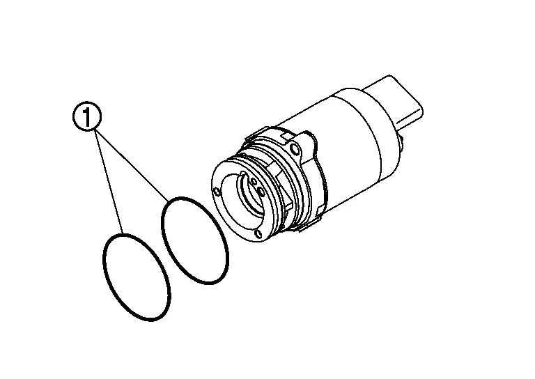
Remove O-rings from actuator assembly.
CAUTION:
-
Never use a tool.
-
Never damage actuator assembly.
Remove O-ring from electro-hydraulic coupling assembly.
CAUTION:
-
Never use a tool.
-
Never damage electro-hydraulic coupling assembly.
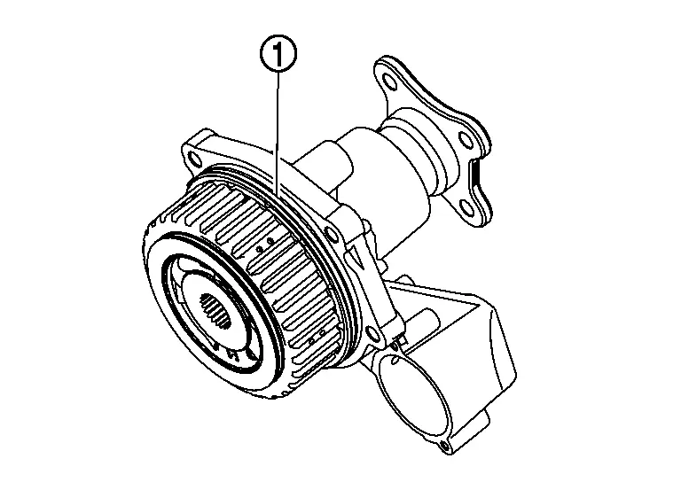
While holding companion flange with the flange wrench (commercial service tool), loosen companion flange lock nut and remove it.
Remove companion flange .
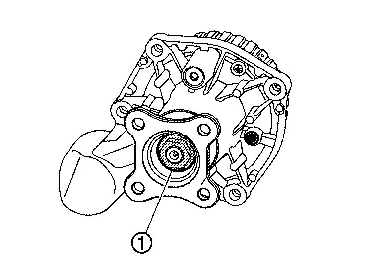
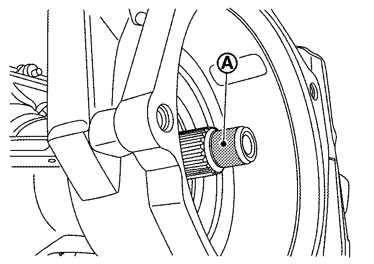
Remove electro-hydraulic coupling oil seal using oil seal remover (A) (commercial service tool).
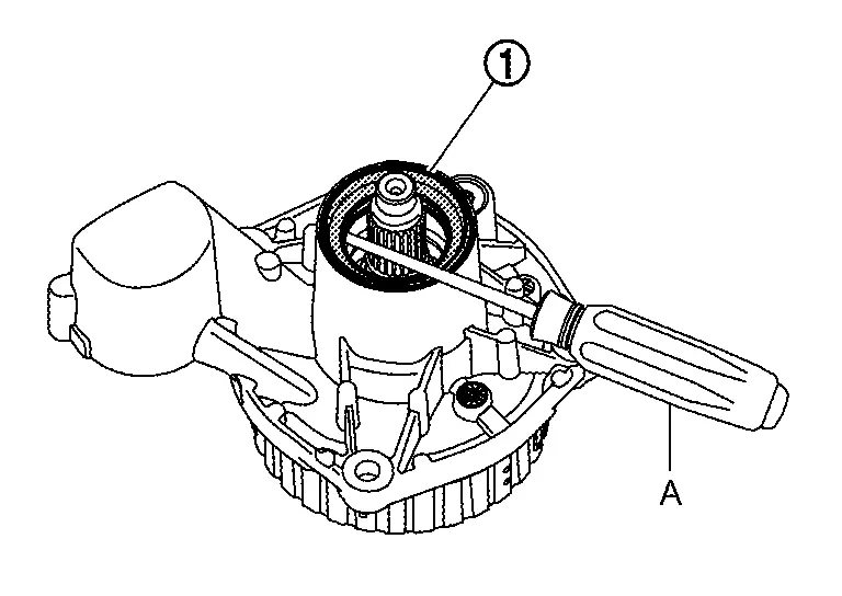
CAUTION:
Never damage electro-hydraulic coupling assembly.
Remove coupling oil tank cover , filler plug , and gasket from gear carrier , if necessary.
Perform inspection after disassembly. Refer to Inspection.
ASSEMBLY
CAUTION:
Be careful to place each part so that the contamination never stick to the drum surface and the mating surface of the companion flange during work.
Using the drift (A) (commercial service tool), install electro-hydraulic coupling oil seal as shown in the figure.
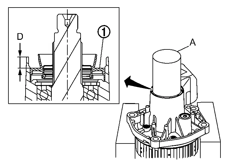
| Installation dimension | |
| D | : 7.15 ±0.1 mm (0.2815 ±0.004 in) |
CAUTION:
-
Never reuse oil seal.
-
When installing, never incline oil seal.
-
Check that the oil seal lip is filled up with grease.
-
Apply electro-hydraulic coupling oil lightly and evenly onto the outer circumference of oil seal.
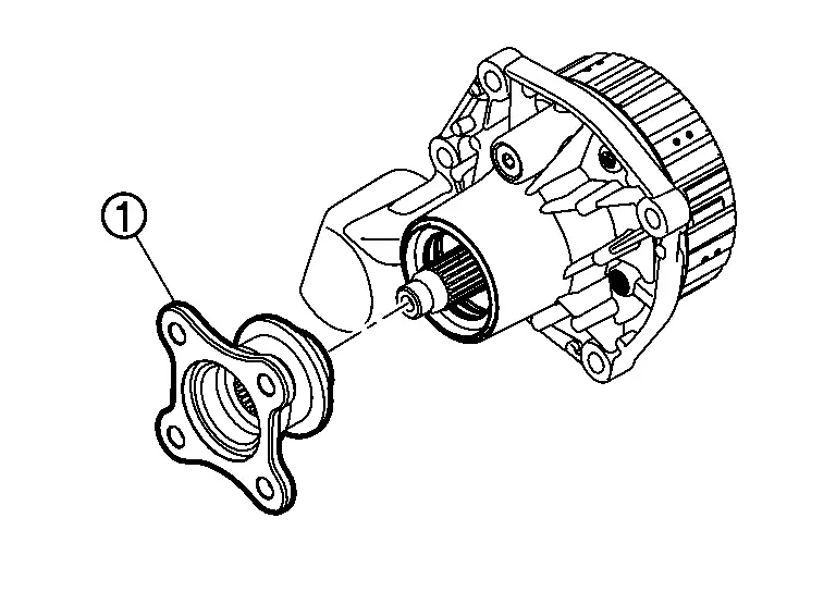
Install companion flange .
CAUTION:
Never reuse companion flange.
While holding companion flange with the flange wrench (commercial service tool), tighten companion flange lock nut to the specified torque.
-
For tightening torque, refer to Exploded View.
CAUTION:
Never reuse companion flange lock nut.
Install O-ring to electro-hydraulic coupling assembly.
CAUTION:
-
Never reuse O-ring.
-
Apply electro-hydraulic coupling oil lightly and evenly onto O-ring.
-
When installing O-ring, never use a tool.
-
Never damage O-ring.
Install O-rings to actuator assembly.
CAUTION:
-
Never reuse O-ring.
-
Apply electro-hydraulic coupling oil lightly and evenly onto O-ring.
-
When installing O-ring, never use a tool.
-
Never damage O-ring.
Set electro-hydraulic coupling assembly in a vertical position before Installing actuator assembly.
Install actuator assembly to electro-hydraulic coupling assembly and tighten mounting bolts evenly to the specified torque.
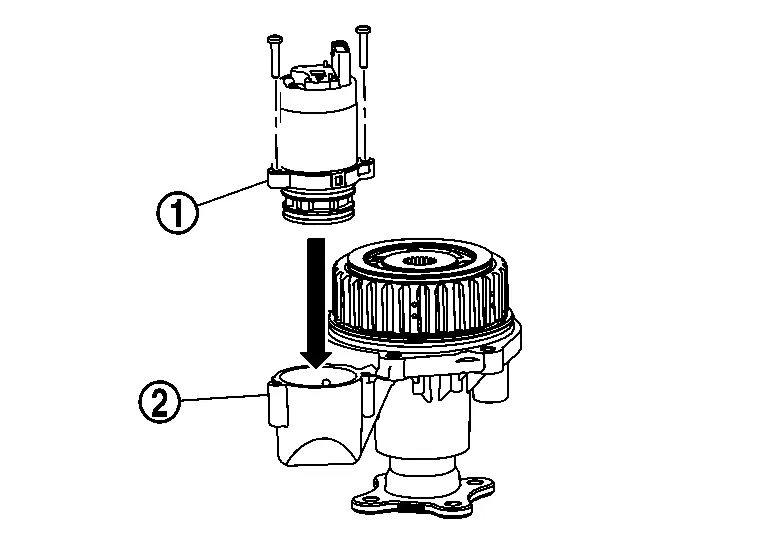
-
For tightening torque, refer to Exploded View.
CAUTION:
-
Never reuse mounting bolt.
-
When assembling actuator assembly to electro-hydraulic coupling housing, never apply radial force to avoid misalignment.
-
Temporarily tightening mounting bolt first. After this, tighten bolts evenly to the specified torque.
Measure and search for the maximum point of drive pinion runout. Refer to Adjustment.
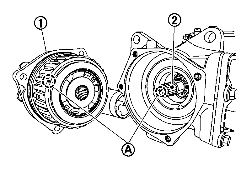
Match electro-hydraulic coupling assembly to spline of drive pinion, then install it to final drive assembly .
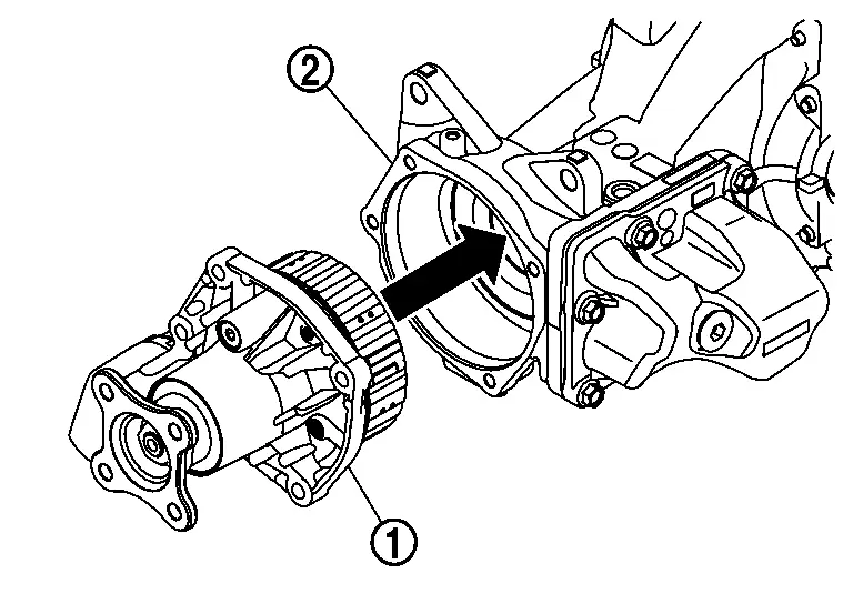
CAUTION:
Aligning marking on drum of electro-hydraulic coupling assembly and marking on tip of drive pinion .
Tighten electro-hydraulic coupling assembly mounting bolts to the specified torque diagonally.
-
For tightening torque, refer to Exploded View.
CAUTION:
Check that electro-hydraulic coupling assembly is seated fully on final drive assembly before installing mounting bolts.
Apply liquid gasket to mating surface of coupling oil tank cover .
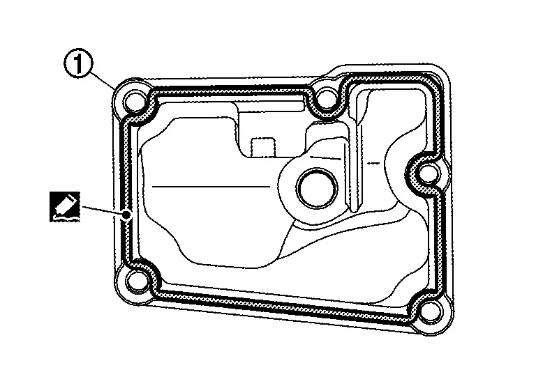
-
For applying liquid gasket, refer to Exploded View.
CAUTION:
-
Remove old gasket adhering to the mounting surfaces. Also remove any moisture, oil, or foreign material adhering to the mounting surfaces.
-
The width of sealant bead is approximately 2.6 mm (0.102 in). Apply sealant evenly.
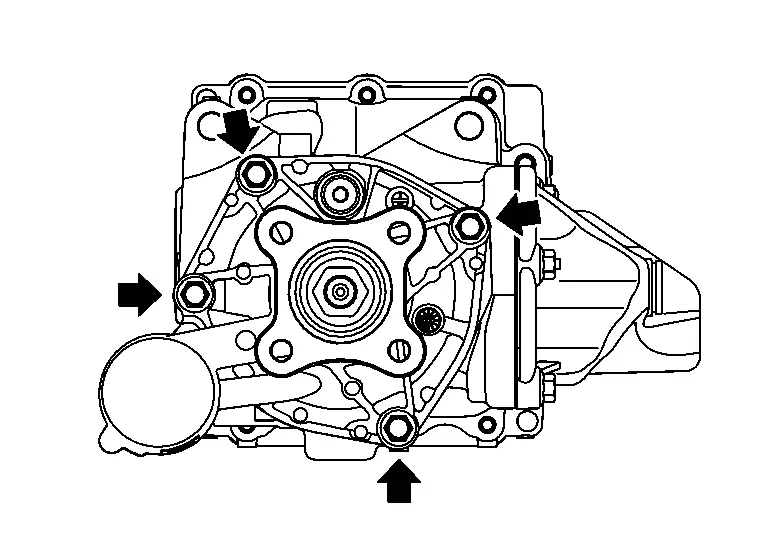
Install coupling oil tank cover to gear carrier and tighten the mounting bolts to the specified torque in the order shown in the figure.
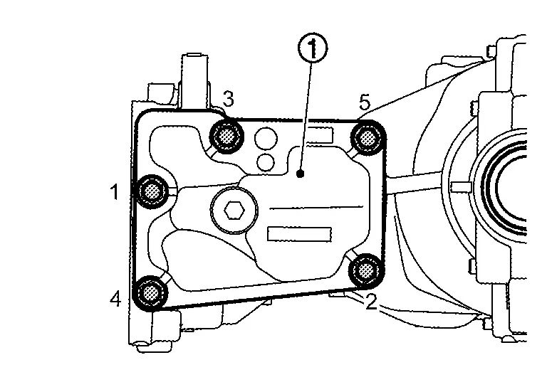
-
For tightening torque, refer to Exploded View.
Check companion flange runout. Refer to Adjustment.
Fill with electro-hydraulic coupling oil after installing final drive assembly or electro-hydraulic coupling assembly to the Nissan Ariya vehicle. Refer to Adjustment.
Adjustment
DRIVE PINION RUNOUT
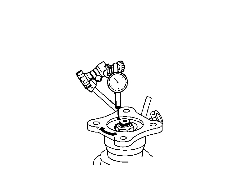
Set pinion nut wrench [SST: KV38109900 (NI-53029)] on drive pinion lock nut.
Fit a test indicator to the part of drive pinion tip.
Rotate the drive pinion with pinion nut wrench [SST: KV38109900 (NI-53029)] to measure drive pinion runout.
| Drive pinion runout | : Refer to Drive Pinion Runout. |
-
If the runout is outside of the repair limit, check drive pinion assembly condition; drive pinion may be deformed etc.
CAUTION:
Replace drive gear and drive pinion as a set.
Search for the maximum point of drive pinion runout and put marking on tip of drive pinion.
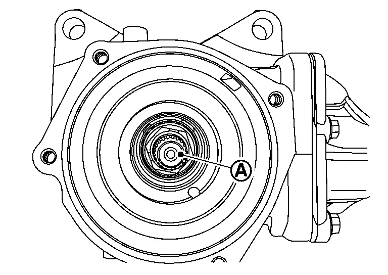
CAUTION:
For marking, use paint. Never damage drive pinion.
COMPANION FLANGE RUNOUT
Fit a dial indicator onto the companion flange face (inner side of the propeller shaft mounting bolt holes).
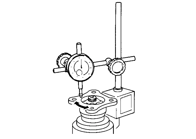
Rotate companion flange to check for runout.
| Companion flange face runout | : Refer to Companion Flange Runout. |
Fit a test indicator to the inner side of companion flange (socket diameter).
Rotate companion flange to check for runout.
| Inner side of the companion flange runout | : Refer to Companion Flange Runout. |
If the runout value is outside the runout limit, follow the procedure below to adjust.Check for runout while changing the phase between companion flange and shaft of electro-hydraulic coupling by 90° step, and search for the position where the runout is the minimum. If the runout value is still outside of the limit after the phase has been changed, replace companion flange. Adjust assembly status of electro-hydraulic coupling, or replace electro-hydraulic coupling assembly if runout is outside the limit after the companion flange is replaced.
Inspection
INSPECTION AFTER DISASSEMBLY
Bearing
-
If unusual noise from the bearing is observed, replace electro-hydraulic coupling assembly.
Oil Seal
-
Whenever disassembled, replace.
-
If wear, deterioration of adherence (sealing force lips), or damage is detected on the lips, replace them.
Companion Flange
-
Whenever disassembled, replace.
-
If any chipped mark [about 0.1 mm, (0.004 in)] or other damage on the contact sides of the lips of the companion flange is found, replace.
Other materials:
B120e-55 Ipdm E/r
DTC Description
DTC DETECTION LOGIC DTC No.
CONSULT screen items
(Trouble diagnosis content) DTC detection condition
B120E-55
IPDM E/R
(Intelligent power distribution module engine room)
[NOT CONFIGURED]
Diagnosis condition
When ignition switch is ON
Signal (terminal)
â ...
Turning the AEB with Pedestrian Detection system ON/OFF
AEB system OFF warning light (on the meter panel)
Vehicle information display
Steering-wheel-mounted controls (left side)
Follow the steps below to switch the AEB with Pedestrian Detection system on or off in your Nissan Rogue.
1. Press the
button until “Settings” appears in the vehicle ...
Its Can Communication 4 Circuit
Diagnosis Procedure
CHECK NETWORK DIAGNOSIS
Check the "Network diagnosis" results from CONSULT to see that the diagnostic CAN communication circuit have no malfunction.
Are the diagnostic CAN communication circuit normal?
YES>>
GO TO 2.
NO>>
Check and repair diagnostic CAN commu ...