Nissan Rogue Service Manual: Electrical load signal
Description
The electrical load signal (Headlamp switch signal, rear window defogger switch signal, etc.) is transferred via the CAN communication.
Component Function Check
1.CHECK REAR WINDOW DEFOGGER SWITCH FUNCTION
- Turn ignition switch ON.
- Connect CONSULT and select “DATA MONITOR” mode.
- Select “LOAD SIGNAL” and check indication under the following conditions.
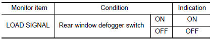
Is the inspection result normal? YES >> GO TO 2.
NO >> Proceed to EC-462, "Diagnosis Procedure".
2.CHECK LIGHTING SWITCH FUNCTION
Check “LOAD SIGNAL” indication under the following conditions.
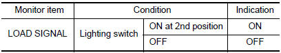
Is the inspection result normal? YES >> GO TO 3.
NO >> Proceed to EC-462, "Diagnosis Procedure".
3.CHECK HEATER FAN CONTROL SWITCH FUNCTION
Select “HEATER FAN SW” and check indication under the following conditions.
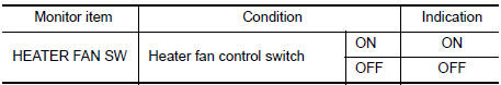
Is the inspection result normal? YES >> INSPECTION END
NO >> Proceed to EC-462, "Diagnosis Procedure".
Diagnosis Procedure
1.INSPECTION START
Confirm the malfunctioning circuit (rear window defogger, headlamp or heater fan). Refer to EC-462, "Component Function Check".
Which circuit is related to the incident? Rear window defogger>>GO TO 2.
Headlamp>>GO TO 3.
Heater fan>>GO TO 4.
2.CHECK REAR WINDOW DEFOGGER SYSTEM
Check rear window defogger system. Refer to DEF-19, "Work Flow".
>> INSPECTION END
3.CHECK HEADLAMP SYSTEM
Check headlamp system. Refer to EXL-82, "Work Flow" (with halogen headlamp) or EXL-219, "Work Flow" (with LED headlamp).
>> INSPECTION END
4.CHECK HEATER FAN CONTROL SYSTEM
Check heater fan control system. Refer to HAC-46, "Work Flow" (with automatic air conditioner) or HAC-146, "Work Flow" (with manual air conditioner).
>> INSPECTION END
 Cooling fan
Component Function Check
1.CHECK COOLING FAN FUNCTION
With CONSULT
Turn ignition switch ON.
Perform “COOLING FAN (DUAL)” in “ACTIVE TEST” mode of “IPDM E/R”
using CO ...
 Fuel injector
Component Function Check
1.INSPECTION START
Turn ignition switch to START.
Are any cylinders ignited?
YES >> GO TO 2.
NO >> Proceed to EC-464, "Diagnosis Procedure".
2. ...
Other materials:
C1604 torque sensor
DTC Logic
DTC DETECTION LOGIC
DTC
Display item
Malfunction detected condition
Possible cause
C1604
TORQUE SENSOR
When torque sensor output signal is malfunctioning.
Harness or connector
Torque sensor
EPS control unit
...
Radiator
RADIATOR CAP
RADIATOR CAP : Inspection
CHECKING RADIATOR CAP
Inspect the radiator cap.
Replace the cap if the metal plunger cannot be seen around the
edge of the black rubber gasket.
Replace the cap if deposits of waxy residue or other foreign
material are on th ...
Oil pan
Exploded View
COMPONENT PARTS LOCATION
Transaxle assembly
Oil pan gasket
Oil pan
Drain plug
Drain plug gasket
Magnet
Overflow plug
O-ring
Always replace after every
disassembly.
: N·m (kg-m, ft-lb)
: N·m (kg-m, in-lb)
: Apply CVT fluid
Removal and Installation ...
