Nissan Rogue Service Manual: Radiator
RADIATOR CAP
RADIATOR CAP : Inspection
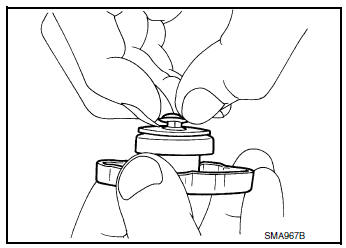
CHECKING RADIATOR CAP
- Inspect the radiator cap.
- Replace the cap if the metal plunger cannot be seen around the edge of the black rubber gasket.
- Replace the cap if deposits of waxy residue or other foreign material are on the black rubber gasket or the metal retainer.
NOTE: Thoroughly wipe out the radiator filler neck to remove any waxy residue or foreign material.
- Pull the negative-pressure valve to open it and check that it closes completely when released.
- Check that there is no dirt or damage on the valve seat of the radiator cap negative-pressure valve.
- Check that there are no abnormalities in the opening and closing conditions of the negative-pressure valve.
- Check radiator cap relief pressure using suitable tool (A/B).
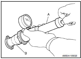
Standard : Refer to CO-25, "Radiator"
- Apply water or engine coolant to the cap seal surface before connecting the radiator cap to the tester.
- Replace the radiator cap if there is an abnormality in the negative- pressure valve, or if the open-valve pressure is outside of the standard values.
RADIATOR
RADIATOR : Inspection
Check radiator for mud or clogging. If necessary, clean radiator as follows.
CAUTION:
- Be careful not to bend or damage radiator fins.
- When radiator is cleaned without removal, remove all surrounding parts such as radiator cooling fan assembly and horns. Then tape harness and harness connectors to prevent water from entering.
- Spray water to the back side of the radiator core using a side to side motion from the top down.
- Stop spraying when debris no longer flows from radiator core.
- Blow air into the back side of radiator core using a side to side motion from the top down.
- Use compressed air lower than 490 kPa (5 kg/cm2, 71 psi) and keep distance more than 30 cm (11.8 in).
- Continue to blow air until no water sprays out.
- Check for engine coolant leaks. Repair as necessary.
 Engine coolant
Inspection
LEVEL
Check that the reservoir tank engine coolant level is within the
“MIN” to “MAX” when the engine is cool.
(A) : MAX
(B) : MIN
Adjust the engine coolant l ...

Other materials:
EVAP canister
Exploded View
EVAP control system pressure sensor
O-ring
EVAP canister
EVAP canister vent control valve
EVAP canister vent control valve hose
EVAP vent line
EVAP canister purge hose
Clamp
Front
Removal and Installation
NOTE:
The EVAP canister vent control val ...
Ignition signal
Component Function Check
1.INSPECTION START
Turn ignition switch OFF, and restart engine.
Does the engine start?
YES-1 >> With CONSULT: GO TO 2.
YES-2 >> Without CONSULT: GO TO 3.
NO >> Proceed to EC-470, "Diagnosis Procedure".
2.CHECK IGNITION SIGNAL FUNCTIO ...
ID registration cannot be completed
Description
The ID of the tire pressure sensor installed in each wheel cannot be
registered in the tire pressure monitoring
system. Inspect the tire pressure sensor or the tire pressure monitoring system
circuit.
Diagnosis Procedure
1.CHECK TIRE PRESSURE SENSOR ACTIVATION TOOL
Check tire pr ...
