Nissan Rogue Service Manual: Fuel injector
Component Function Check
1.INSPECTION START
Turn ignition switch to START.
Are any cylinders ignited? YES >> GO TO 2.
NO >> Proceed to EC-464, "Diagnosis Procedure".
2.CHECK FUEL INJECTOR FUNCTION
 With CONSULT
- Start engine.
- Perform “POWER BALANCE” in “ACTIVE TEST” mode with CONSULT.
- Check that each circuit produces a momentary engine speed drop.
 Without CONSULT
- Start engine.
- Listen to each fuel injector operating sound.
Clicking sound should be heard.
Is the inspection result normal? YES >> INSPECTION END
NO >> Proceed to EC-464, "Diagnosis Procedure".
Diagnosis Procedure
1.CHECK FUEL INJECTOR POWER SUPPLY
- Turn ignition switch OFF.
- Disconnect fuel injector harness connector.
- Turn ignition switch ON.
- Check the voltage between fuel injector harness connector and ground
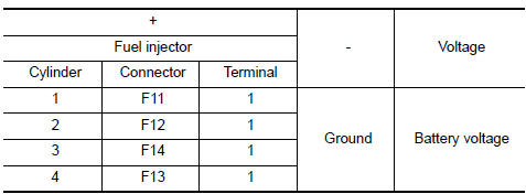
Is the inspection result normal? YES >> GO TO 3.
NO >> GO TO 2.
2.CHECK FUEL INJECTOR POWER SUPPLY CIRCUIT
- Turn ignition switch OFF.
- Disconnect IPDM E/R harness connector.
- Check the continuity between fuel injector harness connector and IPDM E/R harness connector.
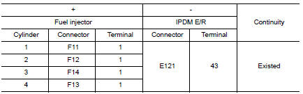
Is the inspection result normal? YES >> Perform the trouble diagnosis for power supply circuit.
NO >> Repair or replace error-detected parts.
3.CHECK FUEL INJECTOR OUTPUT SIGNAL CIRCUIT
- Turn ignition switch OFF.
- Disconnect ECM harness connector.
- Check the continuity between fuel injector harness connector and ECM harness connector.
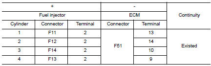
Also check harness for short to ground and to power.
Is the inspection result normal? YES >> GO TO 4.
NO >> Repair open circuit, short to ground or short to power in harness or connectors.
4.CHECK FUEL INJECTOR
Check fuel injector. Refer to EC-465, "Component Inspection".
Is the inspection result normal? YES >> GO TO 5.
NO >> Replace malfunctioning fuel injector. Refer to EM-40, "Exploded View".
5.CHECK INTERMITTENT INCIDENT
Check intermittent incident. Refer to GI-41, "Intermittent Incident".
Is the inspection result normal? YES >> Replace IPDM E/R. Refer to PCS-35, "Removal and Installation".
NO >> Repair or replace error-detected parts.
Component Inspection
1.CHECK FUEL INJECTOR
- Turn ignition switch OFF.
- Disconnect fuel injector harness connector.
- Check resistance between fuel injector terminals as per the following.
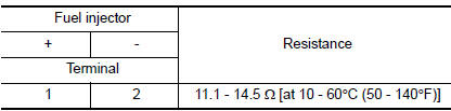
Is the inspection result normal? YES >> INSPECTION END
NO >> Replace malfunctioning fuel injector. Refer to EM-40, "Removal and Installation".
 Electrical load signal
Description
The electrical load signal (Headlamp switch signal, rear window defogger
switch signal, etc.) is transferred via
the CAN communication.
Component Function Check
1.CHECK REAR WINDOW D ...
 Fuel pump
Description
Sensor
Input signal to ECM
ECM Function
Actuator
Crankshaft position sensor (POS)
Camshaft position sensor (PHASE)
Engine speed*
Fuel pump control
Fue ...
Other materials:
Roof rack
Exploded View
Roof rack rear bolt cover
Roof rack front bolt cover
Roof rack
Roof side molding
Back door hinge cover
Metal Clip
Pawl
Removal and Installation
REMOVAL
Release pawls and remove roof rack front and rear cover (1)
using suitable tool (A ...
DTC/circuit diagnosis
U0428 STEERING ANGLE SENSOR
DTC Logic
DTC DETECTION LOGIC
CONSULT Display
DTC Detection Condition
Possible Cause
ST ANG SEN CALIB
[U0428]
Predictive course line center position adjustment
of steering angle sensor is incomplete.
Adjust predictive cours ...
C1143 steering angle sensor
DTC Logic
DTC DETECTION LOGIC
DTC
Display Item
Malfunction detected condition
Possible causes
C1143
ST ANG SEN CIRCUIT
When a malfunction is detected in steering angle sensor.
Harness or connector
Steering angle sensor
ABS actuator and ...
