Nissan Rogue Service Manual: Cooling fan
Component Function Check
1.CHECK COOLING FAN FUNCTION
With CONSULT
- Turn ignition switch ON.
- Perform ŌĆ£COOLING FAN (DUAL)ŌĆØ in ŌĆ£ACTIVE TESTŌĆØ mode of ŌĆ£IPDM E/RŌĆØ using CONSULT.
- Touch ŌĆ£LOWŌĆØ, ŌĆ£HIŌĆØ on the CONSULT screen.
- Check that cooling fan operates.
Is the inspection result normal? YES >> INSPECTION END
NO >> Proceed to EC-458, "Diagnosis Procedure".
Diagnosis Procedure
1.CHECK COOLING FAN RELAY POWER SUPPLY CIRCUIT
- Turn ignition switch OFF.
- Disconnect cooling fan relays-2, -3.
- Turn ignition switch ON.
- Check the voltage between cooling fan relays-2, -3 harness connectors and ground.
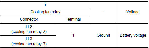
Is the inspection result normal? YES >> GO TO 2.
NO >> Perform trouble diagnosis for power supply circuit.
2.CHECK COOLING FAN MOTOR CIRCUIT-1
Check the voltage between cooling fan relays-2, -3 harness connectors and ground.
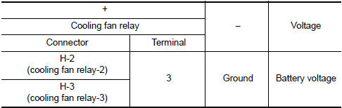
Is the inspection result normal? YES >> GO TO 3.
NO >> GO TO 4.
3.CHECK COOLING FAN RELAY OUTPUT SIGNAL CIRCUIT
- Turn ignition switch OFF.
- Disconnect IPDM E/R harness connectors.
- Check the continuity between cooling fan relay-2, -3 harness connectors and IPDM E/R harness connector.
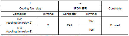
- Also check harness for short to ground and to power.
Is the inspection result normal? YES >> GO TO 6.
NO >> Repair or replace error-detected parts.
4.CHECK COOLING FAN MOTOR POWER SUPPLY CIRCUIT
- Disconnect cooling fan motor-1 harness connector.
- Check the voltage between cooling fan motor-1 harness connector and ground.
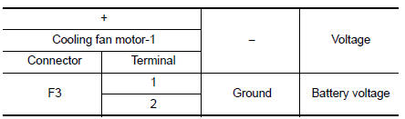
Is the inspection result normal? YES >> GO TO 5.
NO >> Perform trouble diagnosis for power supply circuit.
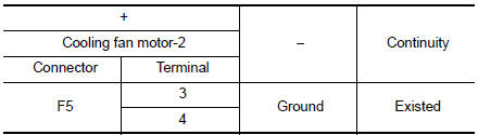
5.CHECK COOLING FAN MOTOR CIRCUIT-2
- Check the continuity between cooling fan relay-2, -3 harness connectors and cooling fan motor-1, -2 harness connectors.
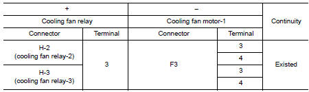
- Also check harness for short to ground and to power.
Is the inspection result normal? YES >> GO TO 11.
NO >> Repair or replace error-detected parts.
6.CHECK COOLING FAN MOTOR CIRCUIT-3
- Check the continuity between IPDM E/R harness connector and cooling fan motor-2 harness connector.
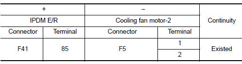
- Also check harness for short to ground and to power.
Is the inspection result normal? YES >> GO TO 7.
NO >> Repair or replace error-detected parts.
7.CHECK COOLING FAN MOTOR CIRCUIT-4
- Check the continuity between cooling fan relay-3 harness connectors and ground.
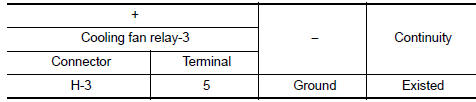
- Also check harness for short to ground and to power.
Is the inspection result normal? YES >> GO TO 8.
NO >> Repair or replace error-detected parts.
8.CHECK COOLING FAN MOTOR CIRCUIT-5
- Check the continuity between cooling fan relay--3 harness connectors and cooling fan motor-2 harness connector.
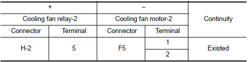
- Also check harness for short to ground and to power.
Is the inspection result normal? YES >> GO TO 9.
NO >> Repair or replace error-detected parts.
9.CHECK COOLING FAN MOTOR CIRCUIT-4
- Check the continuity between cooling fan motor-2 harness connector and ground.
- Also check harness for short to ground and to power.
Is the inspection result normal? YES >> GO TO 10.
NO >> Repair or replace error-detected parts.
10.CHECK COOLING FAN RELAY-2 AND -3
Refer to EC-461, "Component Inspection (Cooling Fan Relay)".
Is the inspection result normal? YES >> GO TO 11.
NO >> Replace malfunctioning cooling fan relay.
11.CHECK COOLING FAN MOTORS-1 AND -2
Refer to EC-461, "Component Inspection (Cooling Fan Motor)".
Is the inspection result normal? YES >> GO TO 12.
NO >> Replace malfunctioning cooling fan motor. Refer to CO-17, "Removal and Installation".
12.CHECK INTERMITTENT INCIDENT
Perform GI-41, "Intermittent Incident".
Is the inspection result normal? YES >> Replace IPDM E/R. Refer to PCS-35, "Removal and Installation".
NO >> Repair or replace error-detected parts.
Component Inspection (Cooling Fan Motor)
1.CHECK COOLING FAN MOTOR
- Turn ignition switch OFF.
- Disconnect cooling fan motor harness connector.
- Supply cooling fan motor terminals with battery voltage and check operation.
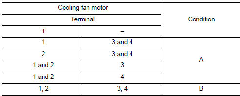
Check that cooling fan speed of condition B is higher than that of A.
Is the inspection result normal? YES >> INSPECTION END
NO >> Replace cooling fan motor. Refer to CO-17, "Removal and Installation".
Component Inspection (Cooling Fan Relay)
1.CHECK COOLING FAN RELAYS
- Turn ignition switch OFF.
- Remove cooling fan relay-2, -3.
- Check the continuity between cooling fan relay-2, -3 terminals as per the following conditions.
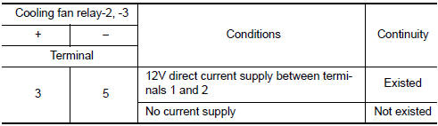
Is the inspection result normal? YES >> INSPECTION END
NO >> Replace cooling fan relay.
 Brake pedal position switch
Component Function Check
1.CHECK BRAKE PEDAL POSITION SWITCH FUNCTION
With CONSULT
Turn ignition switch ON.
Select ŌĆ£BRAKE SW1ŌĆØ in ŌĆ£DATA MONITORŌĆØ mode with CONSULT.
...
 Electrical load signal
Description
The electrical load signal (Headlamp switch signal, rear window defogger
switch signal, etc.) is transferred via
the CAN communication.
Component Function Check
1.CHECK REAR WINDOW D ...
Other materials:
Rear wiper motor circuit
Component Function Check
1. CHECK REAR WIPER ON OPERATION
CONSULT ACTIVE TEST
Select "RR WIPER" of BCM active test item.
While operating the test item, check rear wiper operation.
ON : Rear wiper ON operation
OFF : Stop the rear wiper.
Is rear wiper operation norm ...
Servicing air conditioner
The air conditioner system in your NISSAN vehicle
is charged with a refrigerant designed with
the environment in mind.
This refrigerant does not harm the earthŌĆÖs
ozone layer.
Special charging equipment and lubricant is required
when servicing your NISSAN air conditioner.
Using improper ...
Precaution
Precaution for Supplemental Restraint System (SRS) "AIR BAG" and "SEAT
BELT
PRE-TENSIONER"
The Supplemental Restraint System such as ŌĆ£AIR BAGŌĆØ and ŌĆ£SEAT BELT
PRE-TENSIONERŌĆØ, used along
with a front seat belt, helps to reduce the risk or severity of injury to the
...
