Nissan Rogue Service Manual: Brake pedal position switch
Component Function Check
1.CHECK BRAKE PEDAL POSITION SWITCH FUNCTION
 With CONSULT
- Turn ignition switch ON.
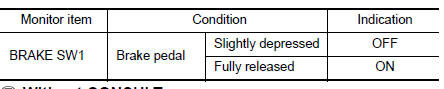
- Select “BRAKE SW1” in “DATA MONITOR” mode with CONSULT.
- Check “BRAKE SW1” indication as per the following conditions.
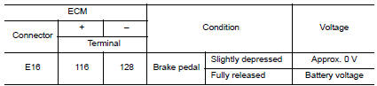
 Without CONSULT
- Turn ignition switch ON.
- Check the voltage between ECM harness connector terminals.
Is the inspection result normal? YES >> INSPECTION END
NO >> Proceed to EC-455, "Diagnosis Procedure".
Diagnosis Procedure
1.CHECK BRAKE PEDAL POSITION SWITCH POWER SUPPLY CIRCUIT
- Turn ignition switch OFF.
- Disconnect brake pedal position switch harness connector.
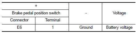
- Turn ignition switch ON.
- Check the voltage between brake pedal position switch harness connector and ground.
Is the inspection result normal? YES >> GO TO 3.
NO >> GO TO 2.
2.CHECK BRAKE PEDAL POSITION SWITCH POWER SUPPLY CIRCUIT
- Turn ignition switch OFF.
- Disconnect fuse block (J/B) harness connector.
- Check the continuity between brake pedal position switch harness connector and fuse block (J/B) harness connector.
Is the inspection result normal? YES >> Perform the trouble diagnosis for power supply circuit.
NO >> Repair or replace error-detected parts.
3.CHECK BRAKE PEDAL POSITION SWITCH INPUT SIGNAL CIRCUIT
- Turn ignition switch OFF.
- Disconnect ECM harness connector.
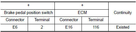
- Check the continuity between brake pedal position switch harness connector and ECM harness connector.
- Also check harness for short to ground and to power.
Is the inspection result normal? YES >> GO TO 4.
NO >> Repair open circuit, short to ground or short to power in harness or connectors.
4.CHECK BRAKE PEDAL POSITION SWITCH
Check brake pedal position switch. Refer to EC-456, "Component Inspection (Brake Pedal Position Switch)".
Is the inspection result normal? YES >> Check intermittent incident. Refer to GI-41, "Intermittent Incident".
NO >> Replace brake pedal position switch. Refer to BR-20, "Exploded View".
Component Inspection (Brake Pedal Position Switch)
1.CHECK BRAKE PEDAL POSITION SWITCH-1
- Turn ignition switch OFF.
- Disconnect brake pedal position harness connector.
- Check the continuity between brake pedal position switch terminals as per the following conditions.
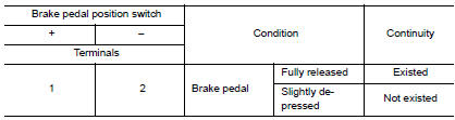
Is the inspection result normal? YES >> INSPECTION END
NO >> GO TO 2.
2.CHECK BRAKE PEDAL POSITION SWITCH-2
- Adjust brake pedal position switch installation. Refer to BR-15, "Adjustment".
- Check the continuity between brake pedal position switch terminals as per the following conditions.
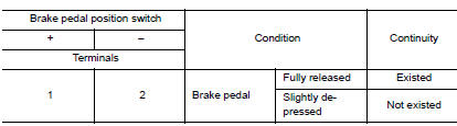
Is the inspection result normal?
YES >> INSPECTION END
NO >> Replace brake pedal position switch. Refer to BR-20, "Exploded View".
 P2610 ECM internal timer
Description
This ECM contains a timer and measures time between an ignition switch OFF
and the next ignition switch
ON. This enables the judging of the state of engine cooling at an engine start.
...
 Cooling fan
Component Function Check
1.CHECK COOLING FAN FUNCTION
With CONSULT
Turn ignition switch ON.
Perform “COOLING FAN (DUAL)” in “ACTIVE TEST” mode of “IPDM E/R”
using CO ...
Other materials:
P0456 EVAP control system
DTC Description
DTC DETECTION LOGIC
This diagnosis detects leaks in the EVAP line between fuel tank and EVAP
canister purge volume control solenoid
valve, using the negative pressure caused by decrease of fuel temperature in the
fuel tank after turning
ignition switch OFF.
If ECM judges t ...
P0606 ECM
DTC Description
DTC DETECTION LOGIC
DTC No.
CONSULT screen terms
(Trouble diagnosis content)
DTC detecting condition
P0606
CONTROL MODULE
(Control module processor)
Malfunction in ECM processor
POSSIBLE CAUSE
ECM
FAIL-SAFE
Not applicable
DTC CONFIRMATION ...
U0101 CAN comm circuit
Description
CAN (Controller Area Network) is a serial communication line for real time
application. It is an on-vehicle multiplex
communication line with high data communication speed and excellent error
detection ability. Many electronic
control units are equipped onto a vehicle, and each co ...
