Nissan Rogue (T33) 2021-Present Service Manual: Ecu Diagnosis Information :: Passenger Door Mirror Control Module
Reference Value
TERMINAL LAYOUT

PHYSICAL VALUES
|
Terminal No. (Wire color) | Description | Condition |
Value (Approx.) | |||
|---|---|---|---|---|---|---|
| (’╝ŗ) | (ŌłÆ) | Signal name | Input/Output | |||
|
1 (BR) |
Ground | Door mirror sensor (passenger side) left/right signal | Input | Door mirror RH position | Change between 6 V (close to left edge) ŌĆÉ 0 V (close to right edge) | |
|
2 (BG) |
Ground | Door mirror sensor (passenger side) up/down signal | Input | Door mirror RH position | Change between 6 V (close to left edge) ŌĆÉ 0 V (close to right edge) | |
|
3 (V) |
Ground | Door mirror motor (passenger side) up output signal | Output | Door mirror RH | Other than above | 0 - 1 V |
| Operate (up) | 9 - 16 V | |||||
|
4 (LA/G) |
Ground | Battery power supply | Input | ŌĆö | 9 - 16 V | |
|
5 (W) |
Ground | Ground (sensor) | ŌĆö | ŌĆö | 0 - 1 V | |
|
6 (R) |
Ground | Door mirror motor sensor power supply | Input | ŌĆö | 4 - 6 V | |
|
7 (L) |
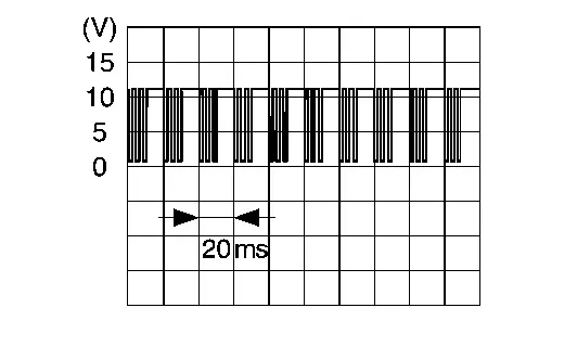
Ground | LIN communication (door mirror) | Input/Output | Ignition switch ON |
|
|
|
10 (P) |
Ground | Door mirror sensor (passenger side) down/right output signal | Output | Door mirror RH | Other than above | 0 - 1 V |
| Operate (down/right) | 9 - 16 V | |||||
|
11 (Y) |
Ground | Door mirror motor (passenger side) left output signal | Output | Door mirror RH | Other than above | 0 - 1 V |
| Operate (left) | 9 - 16 V | |||||
|
12 (B) |
Ground | Ground | ŌĆö | ŌĆö | 0 - 1 V | |
Other materials:
P0011 Ivt Control
DTC Description
DTC DETECTION LOGIC DTC
CONSULT screen terms
(Trouble diagnosis content)
DTC detection condition
P0011
00
INT/V TIM CONT-B1
(ŌĆ£AŌĆØ Camshaft position - timing over-advanced or system performance bank 1)
Diagnosis condition
Engine running
Signal (term ...
System Description. System
Lithium Ion Battery 12v
System Description
SYSTEM DIAGRAM
Component Function
12V sub battery (lithium ion battery)
Refer to 12V Sub Battery (Lithium Ion Battery).
Combination Meter
Receives li-ion battery error signal from 12V sub battery (lithium ion battery) through IPDM E/R via ...
Transfer: Ty92a. System Description
Component Parts
Kr15ddt
Component Parts Location
A.
Transfer case assembly
B.
Rear final drive assembly
No. Component Function
1.
Drive mode switch
Refer to Component Parts Location for detailed component location.
2.
Chassis control module
Chassis contro ...