Nissan Rogue (T33) 2021-Present Service Manual: Ecu Diagnosis Information :: Driver Seat Control Unit
Values on the Diagnosis Tool
 NOTE:
NOTE:
The following table includes information (items) inapplicable to this Nissan Ariya vehicle: For information (items) applicable to this vehicle, refer to CONSULT display items.
| Monitor Item | Condition | Value/Status | |
|---|---|---|---|
| Memory switch 1 | Memory switch-1 | Press | On |
| Release | Off | ||
| Memory switch 2 | Memory switch-2 | Press | On |
| Release | Off | ||
| Set switch | Set switch | Press | On |
| Release | Off | ||
| Reclining switch (Forward) | Reclining switch | Operate (forward) | On |
| Release | Off | ||
| Reclining switch (Backward) | Reclining switch | Operate (backward) | On |
| Release | Off | ||
| Thigh support switch (Up) | Thigh support switch | Operate (upward) | On |
| Release | Off | ||
| Thigh support switch (Down) | Thigh support switch | Operate (downward) | On |
| Release | Off | ||
| Sliding switch (Forward) | Sliding switch | Operate (forward) | On |
| Release | Off | ||
| Sliding switch (Backward) | Sliding switch | Operate (backward) | On |
| Release | Off | ||
| Lifting switch (Up) | Lifting switch | Operate (upward) | On |
| Release | Off | ||
| Lifting switch (Down) | Lifting switch | Operate (downward) | On |
| Release | Off | ||
| Lifting motor position | Seat lifting | Operate (upward) | Change (increase) |
| Operate (downward) | Change (decrease) | ||
| Other than the above | No change | ||
| Reclining motor position | Seat reclining | Operate (forward) | Change (decrease) |
| Operate (backward) | Change (increase) | ||
| Other than the above | No change | ||
| Thigh support motor position | Thigh support | Operate (upward) | Change (increase) |
| Operate (downward) | Change (decrease) | ||
| Other than the above | No change | ||
| Sliding motor position | Seat sliding | Operate (forward) | Change (decrease) |
| Operate (backward) | Change (increase) | ||
| Other than the above | No change | ||
| Memory switch 1 stuck diagnosis | — | Normal | |
| Memory switch 2 stuck diagnosis | — | Normal | |
| Set switch stuck diagnosis | — | Normal | |
| Sliding switch stuck diagnosis | — | Normal | |
| Reclining switch stuck diagnosis | — | Normal | |
| Thigh support switch stuck diagnosis | — | Normal | |
| Lifting switch stuck diagnosis | — | Normal | |
| Massage switch stuck diagnosis | — | Normal | |
| Lumbar support switch stuck diagnosis |
The item is indicated, but not used. |
Normal | |
| Power supply voltage diagnosis (Low voltage) | — | Normal | |
| Power supply voltage diagnosis (High voltage) | — | Normal | |
| Internal power supply voltage diagnosis | — | Normal | |
| Data memory diagnosis | — | Normal | |
| Program memory diagnosis | — | Normal | |
| Calibration/parameter memory diagnosis | — | Normal | |
| Watchdog/safety microcontroller diagnosis | — | Normal | |
| Internal relay stuck diagnosis | — | Normal | |
Reference Value
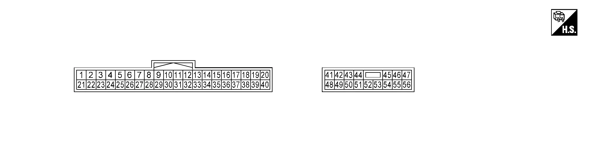
TERMINAL LAYOUT
PHYSICAL VALUES
|
Terminal No. (Wire color) | Description | Condition | Value (Approx.) | |||
|---|---|---|---|---|---|---|
| (+) | (-) | Signal name | Input/output | |||
|
7 (G) |
Ground | Thigh support switch | Input | Thigh support switch | Operate (upward) | 1.524 – 3.268 V |
| Operate (downward) | 0.647 – 1.522 V | |||||
| Release | 3.269 – 4.799 V* | |||||
|
9 (V) |
Ground | Memory switch-1 | Input | Memory switch-1 | Press | 0 – 2 V |
| Release | Battery voltage* | |||||
|
10 (GR) |
Ground | Memory switch-2 | Input | Memory switch-2 | Press | 0 – 2 V |
| Release | Battery voltage* | |||||
|
11 (P) |
Ground | Reclining switch | Input | Reclining switch | Operate (forward) | 1.524 – 3.268 V |
| Operate (backward) | 0.647 – 1.522 V | |||||
| Release | 3.269 – 4.799 V* | |||||
|
12 (SB) |
Ground | Set switch | Input | Set switch | Press | 0 – 2 V |
| Release | Battery voltage* | |||||
|
15 (Y) |
Ground | Thigh support sensor | Input | Thigh support | Operate |
|
| Other than the above | 5 V* | |||||
|
16 (Y) |
Ground | Lifting sensor | Input | Seat lifting | Operate |
|
| Other than the above | 5 V* | |||||
|
18 (G) |
Ground | Memory indicator-2 | Output | Memory indicator-2 | Illuminate | 0 – 1.5 V |
| Other than the above | Battery voltage | |||||
|
19 (W) |
— | CAN-Low | Input/Output | — | — | |
|
20 (P) |
— | CAN-High | Input/Output | — | — | |
|
31 (SB) |
Ground | Sliding / lifting switch | Input | Sliding switch | Operate (forward) | 3.065 – 3.962 V |
| Operate (backward) | 2.638 – 3.064 V | |||||
| Lifting switch | Operate (upward) | 0.789 – 1.755 V | ||||
| Operate (downward) | 0.352 – 0.788 V | |||||
| Sliding / lifting switch release | 3.963 – 4.799 V* | |||||
|
32 (B) |
Ground | Switch ground | — | Always | 0 V | |
|
33 (B) |
Ground | Sensor ground | — | Always | 0 V | |
|
34 (W) |
Ground | Power supply (encoder) | Output | Always | Battery voltage | |
|
35 (LG) |
Ground | Sliding sensor | Input | Seat sliding | Operate |
|
| Other than the above | 5 V* | |||||
|
36 (G) |
Ground | Reclining sensor | Input | Seat reclining | Operate |
|
| Other than the above | 5 V* | |||||
|
38 (Y) |
Ground | Memory indicator-1 | Output | Memory indicator-1 | Illuminate | 0 – 1.5 V |
| Other than the above | Battery voltage | |||||
|
40 (W) |
Ground | LIN communication | Input/Output | Ignition switch ON |
|
|
|
43 (G) |
Ground | Sliding motor LH (forward) | Output | Seat sliding | Operate (forward) | Battery voltage |
| Other than the above | 0 V | |||||
|
44 (W) |
Ground | Sliding motor LH (backward) | Output | Seat sliding | Operate (backward) | Battery voltage |
| Other than the above | 0 V | |||||
|
45 (Y) |
Ground | Lifting motor LH (upward) | Output | Seat lifting | Operate (upward) | Battery voltage |
| Other than the above | 0 V | |||||
|
46 (L) |
Ground | Lifting motor LH (downward) | Output | Seat lifting | Operate (downward) | Battery voltage |
| Other than the above | 0 V | |||||
|
47 (V) |
Ground | Reclining motor LH (forward) | Output | Seat reclining | Operate (forward) | Battery voltage |
| Other than the above | 0 V | |||||
|
48 (R) |
Ground | Battery power supply | — | Always | Battery voltage | |
|
51 (B) |
Ground | Ground | — | Always | 0 V | |
|
52 (GR) |
Ground | Thigh support motor LH (downward) | Output | Thigh support | Operate (downward) | Battery voltage |
| Other than the above | 0 V | |||||
|
53 (B) |
Ground | Thigh support motor LH (upward) | Output | Thigh support | Operate (upward) | Battery voltage |
| Other than the above | 0 V | |||||
|
56 (BR) |
Ground | Reclining motor LH (backward) | Output | Seat reclining | Operate (backward) | Battery voltage |
| Other than the above | 0 V | |||||
*: When the power consumption control of driver seat control unit is in wake-up state.
DTC Index
NOTE:
The details of time display are as follows:
-
CRNT: A malfunction is detected now.
-
PASS: A malfunction was detected in the past.
Ă—: Applicable
| DTC No. | CONSULT display | Fail-safe | Reference |
|---|---|---|---|
| B2900-01 | Sliding/Lifting Switch | — | DTC Description |
| B2906-11 | Recliner Sensor | — | DTC Description |
| B2906-12 | Recliner Sensor | — | DTC Description |
| B2906-31 | Recliner Sensor | — | DTC Description |
| B2907-11 | Lift Sensor | — | DTC Description |
| B2907-12 | Lift Sensor | — | DTC Description |
| B2907-31 | Lift Sensor | — | DTC Description |
| B2908-11 | Slide Sensor | — | DTC Description |
| B2908-12 | Slide Sensor | — | DTC Description |
| B2908-31 | Slide Sensor | — | DTC Description |
| B2909-11 | Slope Sensor | — | DTC Description |
| B2909-12 | Slope Sensor | — | DTC Description |
| B2909-31 | Slope Sensor | — | DTC Description |
| B2920-09 | Driver seat control unit | — | DTC Description |
| B2920-47 | Driver seat control unit | — | DTC Description |
| B2920-48 | Driver seat control unit | — | DTC Description |
| B2920-49 | Driver seat control unit | — | DTC Description |
| B2920-55 | Driver seat control unit | — | DTC Description |
| B2921-A2 | Driver seat control unit | — | DTC Description |
| B2921-A3 | Driver seat control unit | — | DTC Description |
| B2923-55 | Driver seat control unit | — | DTC Description |
Ă—: Applicable
| DTC No. | CONSULT display | Fail-safe | Reference |
|---|---|---|---|
| U2118-87 | CAN comm err (Intelligent Key) | — | DTC Description |
| U2140-87 | CAN comm err (ECM) | — | DTC Description |
| U2141-87 | CAN comm err (TCM) | — | DTC Description |
| U2148-87 | CAN comm err (brake control unit) | — | DTC Description |
| U214E-87 | CAN comm err (combination meter) | — | DTC Description |
| U214F-87 | CAN comm err (BCM) | — | DTC Description |
| U2150-87 | CAN comm err (AIRBAG) | — | DTC Description |
| U2154-87 | CAN comm err (MIU) | — | DTC Description |
| U2156-87 | CAN comm err (steering angel sensor) | — | DTC Description |
| U215B-87 | CAN comm err (IPDM E/R) | — | DTC Description |
| U2195-87 | CAN comm err (SCCM) | — | DTC Description |
| U21B6-87 | CAN comm err (RSCU2R) | — | DTC Description |
Other materials:
Ignition Coil, Spark Plug and Rocker Cover
Exploded View
Ignition coil
Spark plug
Cover (right)
Rocker cover gasket
Rocker cover gasket
Rocker cover
Clamp
Resonator hose
Turbo hose
Blow-by hose
PCV valve
O-ring
Oil filler cap
Oil filler gasket 1
Oil filler gask ...
Switching Signal Circuit
Side Radar Front Rh
Diagnosis Procedure
CHECK CONNECTOR
Turn the ignition switch OFF.
Check the terminals and connectors of the side radar front LH/RH for damage, bend and short (unit side and connector side).
Is the inspection result normal?
YES>>
GO TO 2.
NO>>
...
Service Data and Specifications (sds)
Steering Wheel
Item Standard
Steering wheel axial end play
0 mm (0 in)
Steering wheel play on the outer circumference
0 – 35 mm (0 – 1.38 in)
Steering wheel turning force
34 N (3.5 kg-f, 7.6 lb-f) or less
Steering Angle
Item Standard
Inner wheel
Minimum
...