Nissan Rogue Service Manual: ECU diagnosis information
AWD CONTROL UNIT
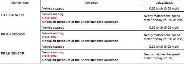
Reference Value
VALUES ON THE DIAGNOSIS TOOL
NOTE: The following table includes information (items) inapplicable to this vehicle. For information (items) applicable to this vehicle, refer to CONSULT display items.
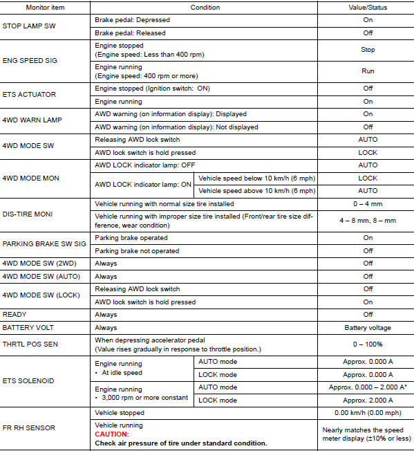
*: The values are changed by throttle opening and engine speed.
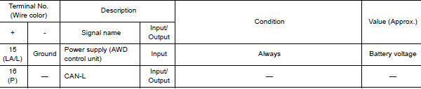
TERMINAL LAYOUT

PHYSICAL VALUES
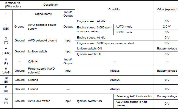
*: The values are changed by depressed accelerator pedal opening and engine speed.
CAUTION: When using circuit tester to measure voltage for inspection, be sure not to extend forcibly any connector terminals.
Fail-Safe
If any malfunction occurs in AWD electrical system, and control unit detects the malfunction, AWD warning on information display (combination meter) is displayed to indicate system malfunction. And then AWD control unit controls becomes the fail-safe mode depending on DTC.
| DTC | Vehicle condition |
|
AWD control changes to front-wheel drive immediately, then AWD control stops, and the vehicle becomes front-wheel drive. |
|
AWD control changes to front-wheel drive immediately, then AWD control stops, and the vehicle becomes front-wheel drive. |
|
No impact to vehicle behavior. |
Protection Function
AWD system activates its protection function (shuts down AWD system temporarily) if AWD system detects high load continuously or the front wheel tire size differs from the rear tire size. (AWD system is automatically restored if AWD system no longer detects any overload or the tire size difference is eliminated.)
| DTC | AWD warning (on information display) | Error area and root cause | Contents of protection function |
| ŌĆö | Refer to DLN-16, "INFORMATION DISPLAY (COMBINATION METER) : AWD Warning". | Rear final drive assembly in protection mode. It is not malfunction.
(Internal temperature rise of electronic controlled coupling) |
Shuts down AWD system temporarily (Front wheel drive) |
| ŌĆö | Malfunction in each tire or different tire diameter |
NOTE:
- If the AWD warning displays during driving but remains not displayed after the engine is restarted, the systemis normal. If it again displays after driving for some time, vehicle must be inspected.
- When there is a difference of revolution speed between the front and rear wheel the shift occasionally changes to direct 4-wheel driving conditions automatically. This is not a malfunction.
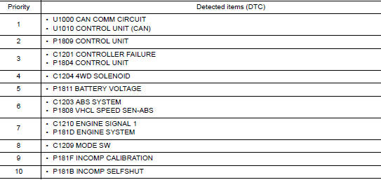
DTC Inspection Priority Chart
If some DTCs are displayed at the same time, perform inspections one by one based on the following priority chart.
DTC Index
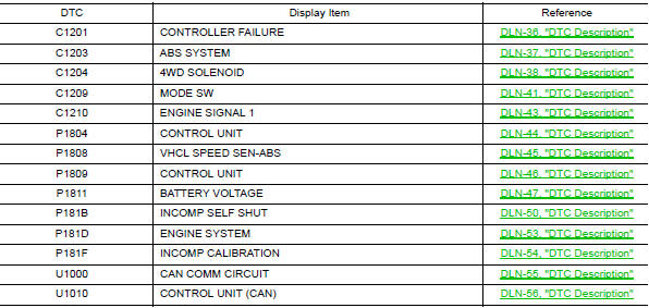
NOTE: If some DTCs are displayed at the same time, refer to DLN-22, "DTC Inspection Priority Chart".
 System description
COMPONENT PARTS
Component Parts Location
Instrument lower panel LH
Rear final drive assembly
Rear wheel house outer panel in luggage
room of left side
No.
Component
Fu ...
 Wiring diagram
AWD SYSTEM
Wiring Diagram
...
Other materials:
Regulatory Information
FCC Regulatory information
CAUTION: To maintain compliance with
FCCŌĆÖs RF exposure guidelines, use only the
supplied antenna. Unauthorized antenna,
modification, or attachments could damage
the transmitter and may violate FCC regulations.
Operation is subject to the follow ...
Operating the power liftgate (if so equipped)
WARNING
Make sure that all passengers have
their hands, etc., inside the vehicle before
closing the liftgate.
Do not leave children unattended inside
the vehicle. They could unknowingly activate
switches or controls. Unattended
children could become inv ...
Recommended fluids and lubricants
Fluids and Lubricants
*1: For additional information, see ŌĆ£Engine Oil RecommendationŌĆØ.
*2: As an alternative to this recommended oil, SAE 5W-30 conventional petroleum
based oil may be used and meet all specifications
and requirements necessary to maintain the New Vehicle Limited Warra ...
