Nissan Rogue Service Manual: Removal and installation
HORN
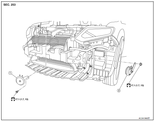
Exploded View

- Horn (LOW)
- Horn (HIGH)
Removal and Installation
REMOVAL
Horn (LOW)
- Remove the front grille. Refer to EXT-23, "Removal and Installation".
- Disconnect the harness connectors from the horn (LOW).
NOTE: Before disconnecting the harness connectors, mark each for proper connection during installation.
- Remove bolt and the horn (LOW).
Horn (HIGH)
- Remove the engine side cover. Refer to EXT-28, "FENDER PROTECTOR : Exploded View".
- Partially remove the fender protector LH (front). Refer to EXT-28, "FENDER PROTECTOR : Exploded View".
- Disconnect the harness connectors from horn (HIGH).
NOTE: Before disconnecting the harness connectors, mark each for proper connection during installation.
- Remove nut and the horn (HIGH).
INSTALLATION
Installation is in the reverse order of removal.
 Wiring diagram
HORN
Wiring Diagram
...
Other materials:
P0643 sensor power supply
Description
ECM supplies a voltage of 5 V to some of the sensors systematically divided
into 2 groups, respectively.
Accordingly, when a short circuit develops in a sensor power source, a
malfunction may occur simultaneously
in the sensors belonging to the same group as the short-circuited ...
Unit disassembly and assembly
TRANSFER COVER
Exploded View
Filler plug
Gasket
Drain plug
Oil seal
Transfer cover
Oil seal
O-ring
Ring gear bearing adjusting shim
(transfer cover side)
Ring gear bearing (transfer cover
side)
Ring gear shaft oil seal
...
Intelligent 4WD (if so equipped)
4X4–I SYSTEM OPERATION
WARNING
Do not drive beyond the performance
capability of the tires. Accelerating
quickly, sharp steering maneuvers or
sudden braking may cause loss of control,
even with Intelligent 4WD engaged.
For 4WD equipped vehicles, do not a ...

