Nissan Rogue Service Manual: System description
COMPONENT PARTS
Component Parts Location
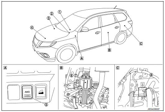
- Instrument lower panel LH
- Rear final drive assembly
- Rear wheel house outer panel in luggage room of left side
| No. | Component | Function |
| 1 | Combination meter | Mainly transmits the following signals to AWD control unit via CAN
communication.
For detailed installation location, refer to MWI-6, "METER SYSTEM : Component Parts Location". |
| 2 | Steering angle sensor | Mainly transmits the following signals to AWD control unit via CAN
communication.
For detailed installation location, refer to BRC-8, "Component Parts Location". |
| 3 | ABS actuator and electric unit (control unit) | Mainly transmits the following signals to AWD control unit via CAN
communication.
For detailed installation location, refer to BRC-8, "Component Parts Location". |
| 4 | ECM | Mainly transmits the following signals to AWD control unit via CAN
communication.
For detailed installation location, refer to EC-14, "Component Parts Location". |
| 5 | AWD lock switch | Refer to DLN-11, "AWD Lock Switch". |
| 6 | Electric controlled coupling | Refer to DLN-11, "Electric Controlled Coupling". |
| 7 | AWD solenoid | Refer to DLN-11, "AWD Solenoid". |
| 8 | AWD control unit
|
Refer to DLN-11, "AWD Control Unit". |
AWD Control Unit
- Controls driving force distribution by signals from each sensor from front wheel driving mode (100:0) to 4- wheel driving mode (50:50).
- Front wheel driving conditions is available by fail-safe function if malfunction is detected in AWD system.
- AWD actuator relay is integrated with AWD control unit, and supplies AWD solenoid with voltag
Electric Controlled Coupling
Electric controlled coupling is integrated with rear final drive and transmits driving force to rear final drive. For operation, refer to DLN-12, "Operation Description".
AWD Solenoid
Controls electric controlled coupling by command current from AWD control unit.
AWD Lock Switch
Every time AWD lock switch is pressed, AUTO mode and LOCK mode switch each other.
STRUCTURE AND OPERATION
Sectional View
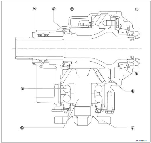
- Transfer cover
- Transfer case
- Ring gear bearing (transfer case side)
- Ring gear shaft
- Pinion bearing
- Drive pinion
- Companion flange
- Ring gear
- Ring gear bearing (transfer cover side)
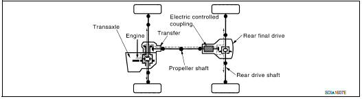
Operation Description
POWER TRANSFER DIAGRAM
ELECTRIC CONTROLLED COUPLING
- The AWD control unit supplies command current to electric controlled coupling (AWD solenoid).
- The control clutch is engaged by electromagnet and torque is detected in control clutch.
- The cam operates in response to control clutch torque and applies pressure to main clutch.
- The main clutch transmits torque to front wheels according to pressing power.
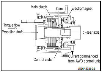
- Transmission torque to the rear wheels is determined according to command current.
SYSTEM
AWD SYSTEM
AWD SYSTEM : System Description
SYSTEM DIAGRAM
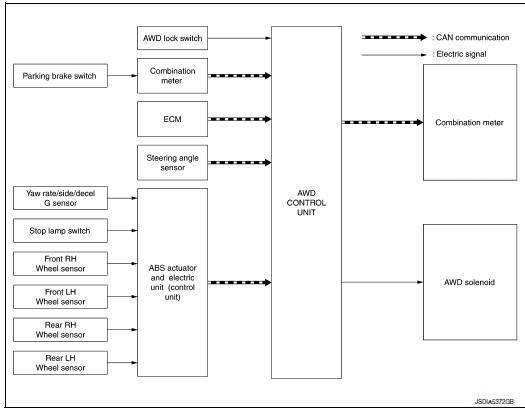
Signal with Communication Line
Major signal transmission between each unit via CAN communication lines are shown in the following table.
| Component parts | Signal item |
| Combination meter | Mainly transmits the following signals to AWD control unit via CAN
communication.
|
| Steering angle sensor | Mainly transmits the following signals to AWD control unit via CAN
communication.
|
| ABS actuator and electric unit (control unit | Mainly transmits the following signals to AWD control unit via CAN
communication.
|
| ECM | Mainly transmits the following signals to AWD control unit via CAN
communication.
|
DESCRIPTION
- AWD controls distribution of drive power between front-wheel drive (100:0) and 4-wheel drive (50:50) conditions according to signals from sensors.
- By receiving the steering angle sensor signal, yaw rate sensor signal, side G sensor signal and decel G sensor signal, vehicle with VDC corrects a torque distribution for front and rear wheels according to a driving operation and a behavior of the vehicle during cornering and improves drivability and safety on a slippery road surface.
- Electronic control allows optimal distribution of torque to front/rear wheels to match road conditions.
- AWD mode makes possible stable driving possible with no wheel spin, on snowy roads or other slippery surfaces.
- On roads which do not require 4-wheel drive, it contributes to improved fuel economy by driving in conditions close to front-wheel drive.
- Sensor inputs determine the vehicle's turning condition, and tight cornering/braking are controlled by distributing optimum torque to rear wheels.
NOTE: Light tight-corner braking symptom may occur depending on driving condition. This is not malfunction.
AWD SYSTEM : Fail-Safe
If any malfunction occurs in AWD electrical system, and control unit detects the malfunction, AWD warning on information display (combination meter) is displayed to indicate system malfunction. And then AWD control unit controls becomes the fail-safe mode depending on DTC.
| DTC | Vehicle condition |
|
AWD control changes to front-wheel drive immediately, then AWD control stops, and the vehicle becomes front-wheel drive. |
|
AWD control changes to front-wheel drive gradually (rear-wheels still have some driving torque), then AWD control stops, and the vehicle becomes front-wheel drive |
|
No impact to vehicle behavior. |
AWD SYSTEM : Protection Function
AWD system activates its protection function (shuts down AWD system temporarily) if AWD system detects high load continuously or the front wheel tire size differs from the rear tire size. (AWD system is automatically restored if AWD system no longer detects any overload or the tire size difference is eliminated.)
| DTC | AWD warning (on information display) | Error area and root cause | Contents of protection function |
| — | Refer to DLN-16, "INFORMATION DISPLAY (COMBINATION METER) : AWD Warning". | Rear final drive assembly in protection mode. It is not malfunction.
(Internal temperature rise of electronic controlled coupling) |
Shuts down AWD system temporarily (Front wheel drive) |
| — | Rear final drive assembly in protection mode. It is not malfunction.
(Internal temperature rise of electronic controlled coupling) |
NOTE:
- If the AWD warning displays during driving but remains not displayed after the engine is restarted, the systemis normal. If it again displays after driving for some time, vehicle must be inspected.
- When there is a difference of revolution speed between the front and rear wheel the shift occasionally changes to direct 4-wheel driving conditions automatically. This is not a malfunction.
INFORMATION DISPLAY (COMBINATION METER)
INFORMATION DISPLAY (COMBINATION METER) : AWD Warning
DESIGN/PURPOSE
AWD warning is displayed when the AWD system has a malfunction. AWD warning indicates that the vehicle is in fail-safe mode or protection function mode.
| Symbol | Message | Condition |
|
|
AWD Error See Owner’s Manual |
AWD system malfunction. |
| AWD Error See Owner’s Manual |
Protection function is activated due to heavy load to electric controlled coupling. (AWD system is not malfunctioning and AWD system changes to rear wheel drive.) | |
| Tire Size Incorrect See Owner’s Manual |
Large difference in diameter of front/rear tires. |

SYNCHRONIZATION WITH MASTER WARNING LAMP
Applicable
For master warning lamp, refer to DLN-17, "WARNING/INDICATOR/CHIME LIST : Warning/Indicator (On Information Display)".
SYSTEM DIAGRAM
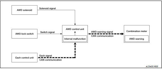
SIGNAL PATH
- The AWD control unit judges and decides a mode from among normal mode, fail-safe mode, and protection function mode, according to signals received from each switch, sensor, and control unit.
- The AWD control unit transmits AWD warning signal to the combination meter via CAN communication when judging fail-safe mode or protection function mode.
- The combination meter displays AWD warning on the information display when receiving AWD warning signal transmitted from the AWD control unit.
WARNING CONDITION
AWD warning is displayed when the AWD system goes into fail-safe mode or protection function mode.
WARNING CANCEL CONDITION
When any of the conditions listed below is satisfied:
- Ignition switch is in a position other than ON.
- AWD warning becomes invisible when the AWD system returns to normal.
WARNING/INDICATOR/CHIME LIST
WARNING/INDICATOR/CHIME LIST : Warning/Indicator (On Information Display)
| Name | Function |
| AWD warning | Refer to DLN-16, "INFORMATION DISPLAY (COMBINATION METER) : AWD Warning". |
DIAGNOSIS SYSTEM (AWD CONTROL UNIT)
CONSULT Function
APPLICATION ITEMS
CONSULT can display each diagnostic item using the diagnostic test modes as follows.
| Diagnostic test mode | Function |
| ECU Identification | AWD control unit part number can be read. |
| Self Diagnostic Result | Self-diagnostic results and freeze frame data can be read and erased quickly.* |
| Data Monitor | Input/Output data in the AWD control unit can be read. |
| Active Test | Diagnostic Test Mode in which CONSULT drives some actuators apart from the AWD control unit and also shifts some parameters in a specified range. |
| Work support | This mode enable a technician to adjust some devices faster and more accurately by following the indication on the CONSULT. |
*: The following diagnosis information is erased by erasing.
- DTC
- Freeze frame data (FFD)
ECU IDENTIFICATION
AWD control unit part number can be read.
SELF DIAGNOSTIC RESULT
Refer to DLN-23, "DTC Index".
When “PRSNT” is displayed on self-diagnosis result.
- The system is presently malfunctioning.
When “PAST” is displayed on self-diagnosis result.
- System malfunction in the past is detected, but the system is presently normal.
FREEZE FRAME DATA (FFD)
The following vehicle status is recorded when DTC is detected and is displayed.
| Monitor item (Unit) | Remarks |
| ODO/TRIP METER [km/h] or [mph] | Odometer value via CAN communication line is displayed. |
| ABS OPERATION SIG [On/Off] | ABS operation status via CAN communication line is displayed. |
| VDC OPERATION SIG [On/Off] | VDC operation status via CAN communication line is displayed. |
| TCS OPERATION SIG [On/Off] | TCS operation status via CAN communication line is displayed. |
| HI COEF FRIC FLG 1 [LOW/HIGH] | Measured friction of load is displayed when vehicle starts. |
| HI COEF FRIC FLG 2 [LOW/HIGH] | Measured friction of load is displayed when vehicle during deceleration. |
| IGN VOLT [V] | Ignition voltage supplied to AWD control unit is displayed. |
| TARGET SOL CRNT [A] | AWD solenoid target current is displayed. |
| SOLENOID CRNT [A] | AWD solenoid control current is displayed. |
| QUASI VEHICLE SPEED [km/h] or [mph] | Vehicle speed calculated by AWD control unit is displayed. |
| FRONT WHEEL SPEED [km/h] or [mph] | Front wheel speed average calculated by AWD control unit is displayed. |
| REAR WHEEL SPEED [km/h] or [mph] | Rear wheel speed average calculated by AWD control unit is displayed. |
| SLCT LVR POSI | Current transmission gear via CAN communication line is displayed. |
| OPERATION MODE | Control status of AWD mode is displayed. |
| FRONT RH WHEEL SPEED [km/h] or [mph] | Wheel speed calculated by front RH wheel sensor signal is displayed. |
| FRONT LH WHEEL SPEED [km/h] or [mph] | Wheel speed calculated by front LH wheel sensor signal is displayed. |
| REAR RH WHEEL SPEED [km/h] or [mph] | Wheel speed calculated by rear RH wheel sensor signal is displayed. |
| REAR LH WHEEL SPEED [km/h] or [mph] | Wheel speed calculated by rear LH wheel sensor signal is displayed. |
DATA MONITOR
NOTE: The following table includes information (items) inapplicable to this vehicle. For information (items) applicable to this vehicle, refer to CONSULT display items.
| Monitor item (Unit) | Remarks |
| STOP LAMP SW [On/Off] | Stop lamp switch signal status via CAN communication line is displayed. |
| ENG SPEED SIG [Run/Stop] | Engine status is displayed. |
| ETS ACTUATOR [On/Off] | Operating condition of AWD actuator relay (integrated in AWD control unit) is displayed |
| 4WD WARN LAMP [On/Off] | Control status of AWD warning (on information display) is displayed. |
| 4WD MODE SW [AUTO/LOCK] | AWD lock switch status is displayed. |
| 4WD MODE MON [AUTO/LOCK] | Control status of AWD is displayed. |
| DIS-TIRE MONI [mm] | Improper size tire installed condition is displayed. |
| PARKING BRAKE SW SIG [On/Off] | Parking switch signal status via CAN communication line is displayed. |
| 4WD MODE SW (2WD) [On/Off] | This item is not equipped, but displayed. |
| 4WD MODE SW (AUTO) [On/Off] | This item is not equipped, but displayed. |
| 4WD MODE SW (LOCK) [On/Off] | AWD lock switch signal is displayed. |
| READY [Off/Running] | This item is not equipped, but displayed. |
| BATTERY VOLT [V] | Power supply voltage value of AWD control unit is displayed. |
| THRTL POS SEN [%] | Throttle opening status is displayed. |
| ETS SOLENOID [A] | Monitored value of current at AWD solenoid is displayed. |
| FR RH SENSOR [km/h] or [mph] | Wheel speed calculated by front RH wheel sensor signal is displayed. |
| FR LH SENSOR [km/h] or [mph] | Wheel speed calculated by front LH wheel sensor signal is displayed. |
| RR RH SENSOR [km/h] or [mph] | Wheel speed calculated by rear RH wheel sensor signal is displayed. |
| RR LH SENSOR [km/h] or [mph] | Wheel speed calculated by rear LH wheel sensor signal is displayed |
ACTIVE TEST
Use this mode to determine and identify the details of a malfunction based on self-diagnostic results or data monitor. AWD control unit gives drive signal to actuator with receiving command from CONSULT to check operation of actuator.
| Test item | Condition | Description |
| SOLENOID (Detects AWD solenoid) |
|
Change command current value to AWD solenoid, and then change
driving
mode. (Monitor value is normal if it is within approx. ±10% of command
value.)
|
CAUTION: Never energize continuously for a long time.
WORK SUPPORT
| Item | Usage |
| UNIT CHARACTERISTICS DATA | Display the unit characteristics of electric controlled coupling written to AWD control unit. |
| UNIT CHARACTERISTICS WRITE | Writes the unit characteristics of electric controlled coupling to AWD control unit. |
 Preparation
Special service tool
The actual shapes of techmate tools may differ from those of special service
tools illustrated here.
Tool number
(techmate no.)
Tool name
Description
...
 ECU diagnosis information
AWD CONTROL UNIT
Reference Value
VALUES ON THE DIAGNOSIS TOOL
NOTE:
The following table includes information (items) inapplicable to this vehicle.
For information (items) applicable
to this veh ...
Other materials:
Symptom diagnosis
MULTI AV SYSTEM
Symptom Table
RELATED TO AUDIO
Symptoms
Check items
Probable malfunction location
The disk cannot be removed.
AV control unit
Malfunction in AV control unit.
Refer to AV-91, "On Board Diagnosis Function".
No sound comes ...
Seat belt extenders
3rd row shown; 2nd row similar
Seat belt hook
When the seat belt is not in use and when folding
down the rear seats, hook the rear seat belts on
the seat belt hooks.
If, because of body size or driving position, it is
not possible to properly fit the lap/shoulder belt
and fasten it, an ex ...
Audio operation precautions
Compact disc (CD) player
CAUTION
Do not force a compact disc into the CD
insert slot. This could damage the CD
and/or CD player.
Trying to load a CD with the CD door
closed could damage the CD and/or CD
player.
Only one CD can be loaded into ...
