Nissan Rogue Service Manual: Preparation
Special service tool
The actual shapes of techmate tools may differ from those of special service tools illustrated here.
| Tool number (techmate no.) Tool name | Description | |
| St33061000
(j-8107-2)
drift a: 38 mm (1.50 In) dia. B: 28.5 Mm (1.122 In) dia. |
 |
Removing gear ring bearing inner race (transfer case side) |
| Kv381054s0 (j-34286) puller |  |
Removing ring gear shaft oil seal |
| St3127s000 (j-25765-a) preload gauge |  |
Measuring preload torque |
Commercial Service Tool
| Tool name | Description | |
| Power tool |  |
Loosening nuts, screws and bolts |
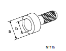
| Drift a: 52 mm (2.05 in) dia. b: 44 mm (1.73 in) dia. |
 |
Removing gear ring bearing inner race (transfer cover side) |
| Drift a: 56.5 mm (2.224 in) dia. b: 48 mm (1.89 in) dia. |
 |
Installing side oil seal (installing transfer case oil seal) |
| Drift a: 44 mm (1.73 in) dia. b: 33 mm (1.3 in) dia. |
 |
Installing ring gear shaft oil seal |
| Puller |  |
Removing ring gear bearing (left) inner race (transfer case side) |
| Drift a: 70 mm (2.76 in) dia. b: 60 mm (2.36 in) dia. |
 |
Installing oil seal (installing pinion bearing seal) |
| Drift a: 78 mm (3.07 in) dia. b: 68 mm (2.68 in) dia. |
 |
Installing side oil seal (installing transfer cover oil seal) |
| Replacer |  |
|
| Drift a: 58 mm (2.28 in) dia. b: 55 mm (2.17 in) dia. |
 |
Installing ring gear bearing (left) inner race (transfer case side) |
| Drift a: 62 mm (2.44 in) dia . b: 58 mm (2.28 in) dia. |
 |
Installing ring gear bearing (right) inner race (transfer cover side) |
| Drift a: 73.5 mm (2.894 in) dia. |
 |
Installing ring gear bearing (left) outer race (transfer case side) |
| Drift a: 87 mm (3.43 in) dia. |
 |
Installing ring gear bearing (right) outer race (transfer cover side) |
| Drift a: 20 mm (0.79 in) dia. |
 |
Removing drive pinion |
| Drift a: 50 mm (1.97 in) dia. b: 41 mm (1.61 in) dia. |
 |
Installing pinion bearing assembly |
| Drift a: 40 mm (1.57 in) dia. b: 25 mm (0.98 in) dia. |
 |
Installing companion flange |
 Precaution
Precaution for supplemental restraint system (srs) "air bag" and "seat
belt
pre-tensioner"
The Supplemental Restraint System such as “AIR BAG” and “SEAT BELT PRE-TENSIONE ...
 System description
COMPONENT PARTS
Component Parts Location
Instrument lower panel LH
Rear final drive assembly
Rear wheel house outer panel in luggage
room of left side
No.
Component
Fu ...
Other materials:
Removal and installation
FRONT WHEEL HUB
Exploded View
Disc brake rotor
Nut retainer
Cotter pin
Wheel stud
Steering knuckle
Splash guard
Wheel hub and bearing
Wheel hub lock nut
Removal and Installation
REMOVAL
Remove front wheel and tire using power tool. Refe ...
Front wiper does not operate
Description
The front wiper does not operate under any operation conditions.
Diagnosis Procedure
Regarding Wiring Diagram information, refer to WW-22, "Wiring Diagram".
1. CHECK WIPER RELAY OPERATION
CONSULT ACTIVE TEST
Select FR WIPER of BCM (WIPER) active test item.
&nb ...
Overdrive control switch
Component Function Check
1.CHECK O/D OFF INDICATOR LAMP FUNCTION
Check O/D OFF indicator lamp turns ON for approx. 2 seconds when ignition
switch turns ON.
Is the inspection results normal?
YES >> GO TO 2.
NO >> Go to TM-181, "Diagnosis Procedure".
2.CHECK OVERDRIVE ...
