Nissan Rogue Service Manual: ECU diagnosis information
AV CONTROL UNIT
Reference Value
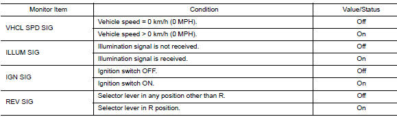
VALUES ON THE DIAGNOSIS TOOL
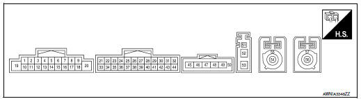
TERMINAL LAYOUT
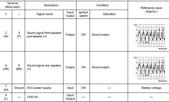
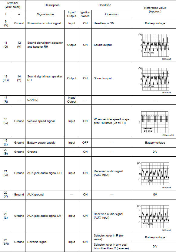
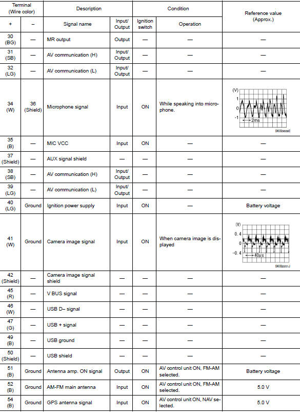
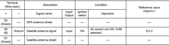
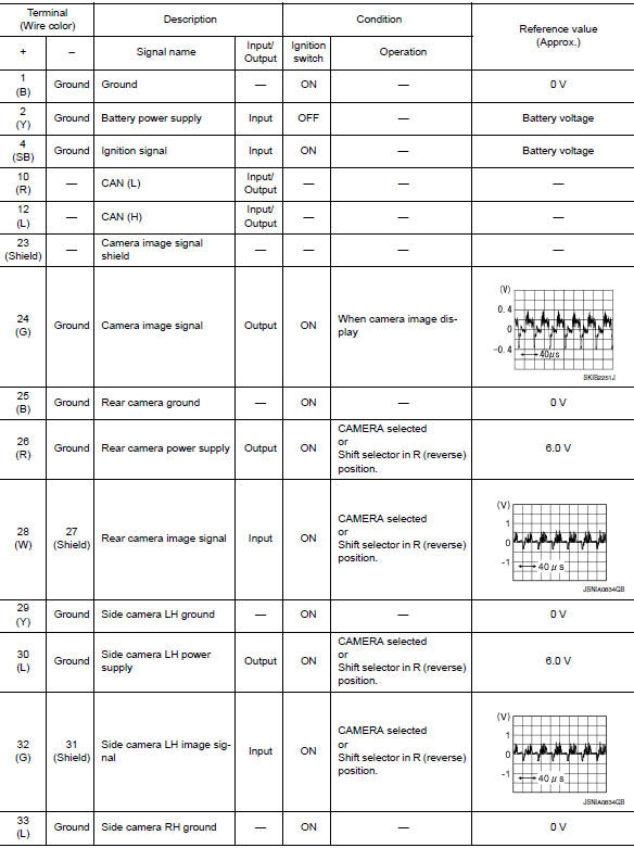
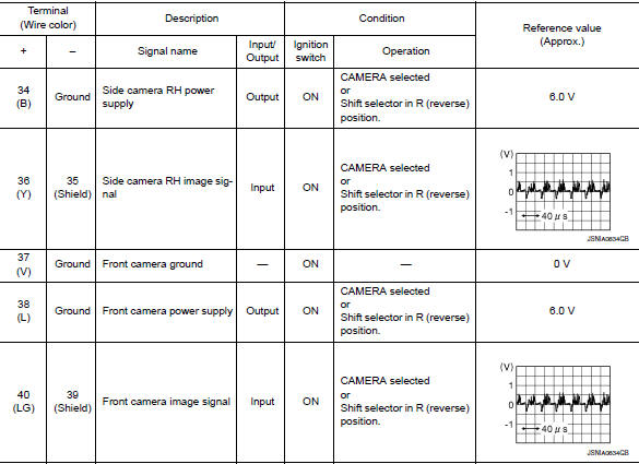
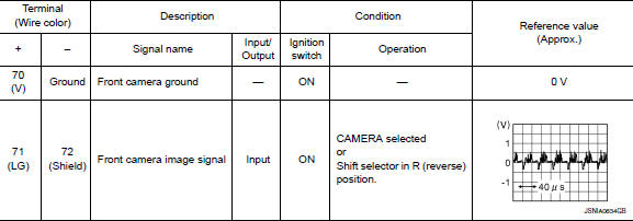
PHYSICAL VALUES
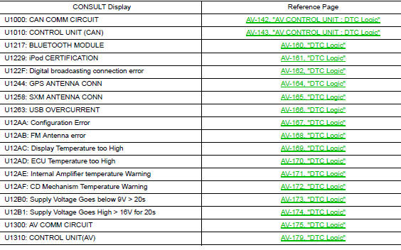
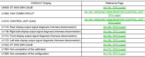
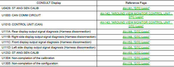
DTC Index
AROUND VIEW MONITOR CONTROL UNIT
WITHOUT DRIVER ASSISTANCE SYSTEM
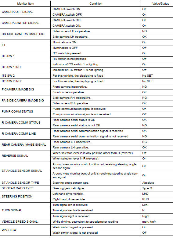
WITHOUT DRIVER ASSISTANCE SYSTEM : Reference Value
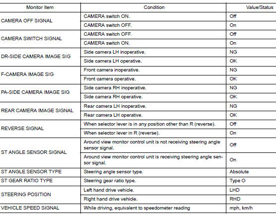
VALUES ON THE DIAGNOSIS TOOL
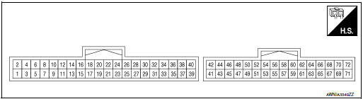
TERMINAL LAYOUT
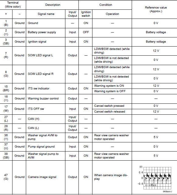
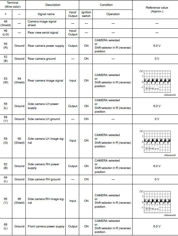
PHYSICAL VALUES
WITHOUT DRIVER ASSISTANCE SYSTEM : DTC Index
WITH DRIVER ASSISTANCE SYSTEM
WITH DRIVER ASSISTANCE SYSTEM : Reference Value
VALUES ON THE DIAGNOSIS TOOL
TERMINAL LAYOUT
PHYSICAL VALUES
WITH DRIVER ASSISTANCE SYSTEM : DTC Index
 System description
COMPONENT PARTS
Component Parts Location
Center of back door
View with glove box removed
No
Component
Function
1
Rod antenna
Refer to AV-232, &qu ...
 Wiring diagram
NAVIGATION WITHOUT BOSE
Wiring Diagram
...
Other materials:
The steering switches are inoperative
Description
One or more of the steering switches to control the information display are
inoperative.
Diagnosis Procedure
1.CHECK STEERING SWITCH CIRCUIT
Check steering switch circuit. Refer to MWI-69, "Diagnosis Procedure".
Is the inspection result normal?
YES >> GO TO 2.
...
Symptom diagnosis
COMBINATION SWITCH SYSTEM SYMPTOMS
Symptom Table
Perform the data monitor of CONSULT to check for any malfunctioning
item.
Check the malfunction combinations.
Identify the malfunctioning part from the agreed combination and repair
or replace the part.
NORMAL OPERATING C ...
Precaution
Precaution for Supplemental Restraint System (SRS) "AIR BAG" and "SEAT
BELT
PRE-TENSIONER"
The Supplemental Restraint System such as “AIR BAG” and “SEAT BELT PRE-TENSIONER”,
used along
with a front seat belt, helps to reduce the risk or severity of injury to the
...
