Nissan Rogue (T33) 2021-Present Service Manual: Ecm
Values On The Diagnosis Tool
VALUES ON THE DIAGNOSIS TOOL
 NOTE:
NOTE:
-
The following table includes information (items) inapplicable to this Nissan Ariya vehicle. For information (items) applicable to this vehicle, refer to CONSULT display items.
-
Numerical values in the following table are reference values.
-
These values are input/output values that ECM receives/transmits and may differ from actual operations.
Example: The ignition timing shown by the timing light may differ from the ignition timing displayed on the data monitor.
This occurs because the timing light shows a value calculated by ECM according to signals received from the camshaft position sensor and other sensors related to ignition timing.
-
For outlines of following items, refer to CONSULT Function.
| Monitor Item | Condition | Values/Status | |
|---|---|---|---|
| Coolant temperature | Engine: After warming up | More than 70┬░C | |
| Nissan Ariya Vehicle speed sensor | Turn drive wheels and compare CONSULT value with the speedometer indication. | Almost the same speed as speedometer indication | |
| BATTERY VOLT | Ignition switch: ON (Engine stopped) | 11 ŌĆō 14 V | |
| EGR TEMP SEN | Engine: After warming up | Less than 4.8 V | |
| Intake air temperature | Engine: After warming up | Indicates intake air temperature | |
| Ignition timing |
|
Idle | 0 deg |
| 2,000 rpm | 35 deg | ||
| ADM/V motor opening angle | Ignition switch: ON | 11.5 deg | |
| ADMV motor position sensor | Ignition switch: ON | 1.02 V | |
| Turbo boost presure sensor |
|
|
3.07 - 3.15 V |
|
|
3.07 - 3.15 V | |
| Purge control solenoid valve |
|
Idle (Accelerator pedal: Not depressed even slightly, after engine starting) |
37 % |
| 2,000 rpm | 1 ŌĆō 100 % | ||
| Fuel tank temperature sensor |
|
Indicates fuel tank temperature | |
| Speed limiter target Nissan Ariya vehicle speed |
|
Depending on fuel level of fuel tank | |
| EVAP system pressure |
|
Approx. 1.8 ŌĆō 4.8 V | |
| Calculated load value |
|
Idle | 5 ŌĆō 35 % |
| 2,500 rpm | 5 ŌĆō 35 % | ||
| Heater oxygen sensor 2 (bank 1) |
|
Revving engine from idle up to 3,000 rpm quickly | 0 ŌĆō 0.3 V ŌåÉŌåÆ 0.6 ŌĆō 1.0 V |
| LEAN ŌåÉŌåÆ RICH | |||
| Engine oil temperature | Engine: After warming up | Indicates engine oil temperature | |
| Barometric pressure sensor | Ignition switch: ON | Approx. 4.14 V | |
| Manifold absolute pressure sensor |
|
Idle | Approx. 1.60 V |
| 2,000 rpm | Approx. 0.86 V | ||
| Air fuel ratio compensation (bank 1) | Diagnosis Procedure | ||
| A/F S1 HTR (B1) |
Engine: After warming up, idle the engine (More than 140 seconds after starting engine) |
4 ŌĆō 100% | |
| EGR differential pressure | Engine: After warming up | Idle | Approx. 1 kPa |
| 2,000 rpm | Approx. 1 kPa | ||
| 4,000 rpm | Approx. 3 kPa | ||
| Exhaust VTC angle (bank 1) |
|
Idle | ŌłÆ5 ŌĆō 5 ┬░CA |
| Around 2,500 rpm while the engine speed is rising | 0 ŌĆō 30 ┬░CA | ||
| Wastegate valve closed position learning bank 2 | Learning is incomplete. There is no memory of the full close position voltage in the ECM. | INCMP | |
| Learning is complete. Full close position voltage is memory in the ECM. | CMPLT | ||
| Wastegate valve closed position learning bank 1 | Learning is incomplete. There is no memory of the full close position voltage in the ECM. | INCMP | |
| Learning is complete. Full close position voltage is memory in the ECM. | CMPLT | ||
| EGR valve position | Ignition switch: ON | 0.0 deg | |
| Engine: Idle | 0.0 deg | ||
| Wastegate actuator position bank 1 |
|
Idle | Approx. 0.0149 m |
| 2,000 rpm | Approx. 0.0150 m | ||
| Charge air cooler coolant temp | Engine: Running | Indicates charge air cooler temperature | |
| Fan duty |
|
0 - 100% | |
| Fuel pump duty |
|
Idle | Approx. 37 % |
| THRTL STK CNT B1 |
This item is displayed but are not applicable to this model. |
ŌĆö | |
| A/GRLL SHTTR POSITION |
|
F/OPEN | |
|
Nissan Ariya Vehicle speed: 30 km/h (19 MPH) or faster. (Comply the condition of active grille shutter operation.) |
F/OPEN ŌåÆMOVINGŌåÆF/ CLOSE | ||
| ENG SPEED |
|
Almost the same speed as the tachometer indication. | |
| Travel after MIL ON | Ignition switch: ON | 0 ŌĆō 65,535 km | |
| Mass air flow sensor bank 1 | Diagnosis Procedure | ||
| Base fuel schedule | Diagnosis Procedure | ||
| Mass air flow sensor |
This item is displayed but are not applicable to this model. |
ŌĆö | |
| FUEL PRES SEN | Ignition switch: ON | Approx. 0 MPa | |
|
Idle | Approx. 11.56 MPa | |
| Accelerate sensor 1 | Ignition switch: ON (Engine stopped) | Accelerator pedal: Fully released | 0.5 ŌĆō 1.0 V |
| Accelerator pedal: Fully depressed | 4.2 ŌĆō 4.8 V | ||
| Accelerate sensor 2* | Ignition switch: ON (Engine stopped) | Accelerator pedal: Fully released | 0.5 ŌĆō 1.0 V |
| Accelerator pedal: Fully depressed | 4.2 ŌĆō 4.8 V | ||
| Throttle sensor 1 (bank 1) |
|
Accelerator pedal: Fully released | More than 0.36 V |
| Accelerator pedal: Fully depressed | Less than 4.75 V | ||
| Throttle sensor 2 (bank 1)* |
|
Accelerator pedal: Fully released | More than 0.36 V |
| Accelerator pedal: Fully depressed | Less than 4.75 V | ||
| Input pully speed |
|
Nissan Ariya Vehicle speed: More than 20 km/h (12 MPH) | Almost the same speed as the tachometer indication |
| Nissan Ariya Vehicle speed | Turn drive wheels and compare CONSULT value with the speedometer indication. | Almost the same speed as the speedometer indication | |
| AC pressure sensor |
|
1.0 ŌĆō 4.0 V | |
| Air/Fuel sensor1 (bank 1) | Engine: After warming up | Maintaining engine speed at 2,000 rpm | Fluctuates around 2.2 V |
| Nissan Ariya Vehicle speed sensor | Turn drive wheels and compare CONSULT value with the speedometer indication. | Almost the same speed as speedometer indication | |
| Exhaust VTC (bank 1) |
|
Idle | 0 % |
| When revving engine up to 2,000 rpm quickly | Approx. 0 ŌĆō 90 % | ||
| Air fuel ratio adjustment (bank 1) | Engine: Idle | ŌłÆ0.450 ŌĆō 0.330 | |
| Intake VTC angle (bank 1) |
|
Idle | 35 ŌĆō 45 ┬░CA |
| 2,000 rpm | Approx. 0 ŌĆō 20 ┬░CA | ||
| High/Pressure fuel pump angle |
|
Idle | 255 ŌĆō 275 deg |
| 2,000 rpm | 255 ŌĆō 275 deg | ||
| Fuel pressure sensor voltage |
|
Idle | 0.820 ŌĆō 1.140 V |
| When revving engine up to 4,000 rpm quickly | 0.820 ŌĆō 2.900 V | ||
| Engine oil pressure sensor |
|
Idle | Approx. 1.360 V |
| 2,000 rpm | Approx. 1.670 V | ||
| EGR valve position sensor | Ignition switch: ON | 0.50 V | |
| Charge air cooler temperature sensor bank 1 | Ignition switch: ON | 0 mV | |
| Wastegate actuator position sensor bank 1 | Engine: After warming up | Idle | Approx. 4.195 V |
| 2,000 rpm | Approx. 4.230 V | ||
| Engine coolant bypass valve position |
|
Approx. 197.9 deg | |
| Engine: Idle | Engine coolant temperature: 64┬░C (148┬░F) | Approx. 63 deg | |
| Engine coolant temperature: 75┬░C (167┬░F) | Approx. 99 deg | ||
| Engine coolant temperature: 86-100┬░C (187- 212┬░F) | Approx. 163 deg | ||
| TOTAL DISTNC-OCS RST 1 | Ignition switch: ON | Varies depending on Nissan Ariya vehicle environment. |
0 - 655,350 km (0 - 407,234 miles) |
| TOTAL DISTNC-OCS RST 2 | Ignition switch: ON | Varies depending on Nissan Ariya vehicle environment. |
0 - 655,350 km (0 - 407,234 miles) |
| TOTAL DISTNC-OCS RST 3 | Ignition switch: ON | Varies depending on Nissan Ariya vehicle environment. |
0 - 655,350 km (0 - 407,234 miles) |
| DETERIORTN VL-OCS RST 1 | Ignition switch: ON | Varies depending on Nissan Ariya vehicle environment. | 0 - 655.35 |
| DETERIORTN VL-OCS RST 2 | Ignition switch: ON | Varies depending on Nissan Ariya vehicle environment. | 0 - 655.35 |
| DETERIORTN VL-OCS RST 3 | Ignition switch: ON | Varies depending on Nissan Ariya vehicle environment. | 0 - 655.35 |
| TOTAL DISTNC-OCS WRN 1 | Ignition switch: ON | Varies depending on Nissan Ariya vehicle environment. |
0 - 655,350 km (0 - 407,234 miles) |
| TOTAL DISTNC-OCS WRN 2 | Ignition switch: ON | Varies depending on Nissan Ariya vehicle environment. |
0 - 655,350 km (0 - 407,234 miles) |
| TOTAL DISTNC-OCS WRN 3 | Ignition switch: ON | Varies depending on Nissan Ariya vehicle environment. |
0 - 655,350 km (0 - 407,234 miles) |
| DETERIORIN VL-OCS WRN 1 | Ignition switch: ON | Varies depending on Nissan Ariya vehicle environment. | 0 - 655.35 |
| DETERIORIN VL-OCS WRN 2 | Ignition switch: ON | Varies depending on Nissan Ariya vehicle environment. | 0 - 655.35 |
| DETERIORIN VL-OCS WRN 3 | Ignition switch: ON | Varies depending on Nissan Ariya vehicle environment. | 0 - 655.35 |
| CURRENT DETERIORANT VAL | Ignition switch: ON | Varies depending on Nissan Ariya vehicle environment. | 0 - 655.35 |
| Engine basis parts value 1 |
This item is displayed but are not applicable to this model. |
ŌĆö | |
| Engine basis parts value 2 |
This item is displayed but are not applicable to this model. |
ŌĆö | |
| Electric water pump 1 duty |
|
Idle | Approx. 40% |
| Injection total fuel mass (B1) |
|
Idle | Indicates the total fuel injection volume computed by ECM according to the input signals. |
| Cylinder intake air mass |
|
Idle | Indicates the intake air volume computed by ECM according to the input signals. |
| Lower limit int air mass (IDLE) |
|
Idle | Indicates the lower limit of intake air volume computed by ECM according to the input signals. |
| Upper limit int air mass (IDLE) |
|
Idle | Indicates the upper limit of intake air volume computed by ECM according to the input signals. |
| LOAD SIGNAL | Ignition switch: ON | Rear window defogger switch: ON and/or Lighting switch: 2nd position | On |
| Rear window defogger switch and lighting switch: OFF | Off | ||
| AIR COND SIG | Engine: After warming up, idle the engine | Air conditioner switch: OFF | Off |
|
Air conditioner switch: ON (Compressor operates) |
On | ||
| PW/ST SIGNAL | Engine: After warming up, idle the engine | Steering wheel: Not being turned | Off |
| Steering wheel: Being turned | On | ||
| P/N POSI SW | Ignition switch: ON | Selector lever: P or N position | On |
| Selector lever: Except above position | Off | ||
| START SIGNAL | Ignition switch: ON ŌåÆ START ŌåÆ ON | Off ŌåÆ On ŌåÆ Off | |
| CLSD THL POS | Ignition switch: ON (Engine stopped) | Accelerator pedal: Fully released | On |
| Brake pedal: Slightly depressed | Off | ||
| HO2S2 MNTR(B1) |
|
Revving engine from idle up to 3,000 rpm quickly | LEAN ŌåÉŌåÆ RICH |
| IGNITION SW | Ignition switch: ON ŌåÆ OFF ŌåÆ ON | On ŌåÆ Off ŌåÆ On | |
| HEATER FAN SW | Engine: After warming up, idle the engine | Blower fan switch: ON | On |
| Blower fan switch: OFF | Off | ||
| IDL A/V LEARN |
|
Idle air volume learning has already been performed successfully. | CMPLT |
| Idle air volume learning has not been performed yet. | YET | ||
| Brake switch | Ignition switch: ON | Brake pedal: Fully released OFF | Off |
| Brake pedal: depressed | On | ||
| COMBUSTION |
This item is displayed but are not applicable to this model. |
ŌĆö | |
| AIR COND RLY | Engine: After warming up, idle the engine | A/C switch: OFF | Off |
|
A/C switch: ON (Compressor operates) |
On | ||
| Fuel pump relay RLY |
|
On | |
| Except above | Off | ||
| FPCM | Ignition switch: OFF | Off | |
|
Low | ||
|
Mid | ||
| Engine: Cranking | Hi | ||
| VENT CONT/V | Ignition switch: ON | Off | |
| HO2S2 HTR(B1) | Ignition switch: ON | Off | |
| Brake operation judgment | Ignition switch: ON | Off | |
| DIST SW | Ignition switch: ON | DISTANCE switch: Pressed | On |
| DISTANCE switch: Released | Off | ||
|
Brake switch2 (Stop lamp switch) |
Ignition switch: ON | Brake pedal: Fully released | Off |
| Brake pedal: Depressed | On | ||
|
Brake switch1 (Stop lamp switch) |
Ignition switch: ON | Brake pedal: Fully released | On |
| Brake pedal: Depressed | Off | ||
| SET SW | Ignition switch: ON | SETŌłÆ switch: Pressed | On |
| SETŌłÆ switch: Released | Off | ||
| RESUME/ACC SW | Ignition switch: ON | RES+ switch: Pressed | On |
| RES+ switch: Released | Off | ||
| CANCEL SW | Ignition switch: ON | CANCEL switch: Pressed | On |
| CANCEL switch: Released | Off | ||
| MAIN SW | Ignition switch: ON | ASCD/ProPILOT Assist 1.1/2.1 MAIN switch: Pressed | On |
| ASCD/ProPILOT Assist 1.1/2.1 MAIN switch: Released | Off | ||
| CRUISE LAMP | Ignition switch: ON | ASCD switch: Pressed at the 1st time ŌåÆ at the 2nd time | On ŌåÆ Off |
| A/GRLL SHTTR CALIBRATION |
|
CMPLT | |
|
INCMP | ||
| A/GRLL SHTTR CIRCUIT DIAG | Malfunction of active grill shutter power supply is detected. | NG | |
| Malfunction of active grill shutter power supply is not detected. | OK | ||
| A/GRLL SHTTR TEMP DIAG | Abnormal temperature of active grill shutter actuator is detected. | NG | |
| Abnormal temperature of active grill shutter actuator is not detected. | OK | ||
| A/GRLL SHTTR OVERRUN | Active grill shutter does not stop within normal moving limit. | NG | |
| Active grill shutter stops within normal moving limit. | OK | ||
| A/GRLL SHTTR STUCK | Detecting the active grille shutter stuck or the operation range less than normal. | NG | |
| Not detecting the active grille shutter stuck or the operation range less than normal. | OK | ||
| A/GRLL SHTTR CALIB DIAG | Malfunction of active grill shutter initial position learning is detected. | NG | |
| Malfunction of active grill shutter initial position learning is not detected. | OK | ||
| HO2 S2 DIAG1 (B1) | DTC P0139 self-diagnosis (delayed response) is incomplete. | INCMP | |
| DTC P0139 self-diagnosis (delayed response) is complete. | CMPLT | ||
| HO2 S2 DIAG2 (B1) | DTC P0139 self-diagnosis (slow response) is incomplete. | INCMP | |
| DTC P0139 self-diagnosis (slow response) is complete. | CMPLT | ||
| EVAP LEAK DIAG | Ignition switch: ON | Depending on condition of EVAP leak diagnosis | |
| EVAP DIAG READY | Ignition switch: ON | Depending on ready condition of EVAP leak diagnosis | |
| SYSTEM 1 DIAGNOSIS A B1 | DTC P219A self-diagnosis is incomplete. | INCMP | |
| DTC P219A self-diagnosis is complete. | CMPLT | ||
| A/F SEN1 DIAG1(B1) | DTC P015A and P015B self-diagnosis incomplete. | INCMP | |
| DTC P015A and P015B self-diagnosis is complete. | CMPLT | ||
| A/F SEN1 DIAG2 (B1) | DTC P014C and P014D self-diagnosis incomplete. | INCMP | |
| DTC P014C and P014D self-diagnosis is complete. | CMPLT | ||
| SYSTEM 1 DIAGNOSIS B B1 | DTC P219A self-diagnosis is on standby. | ABSENT | |
| DTC P219A self-diagnosis is under diagnosis. | PRSENT | ||
| A/F IMBALNC DIAG-CPS STAT | The Nissan Ariya vehicle condition is not within the diagnosis range of DTC P219C - P219F. | ABSENT | |
| The Nissan Ariya vehicle condition is within the diagnosis range of DTC P219C - P219F. | PRSENT | ||
| A/F SEN1 DIAG3(B1) | The Nissan Ariya vehicle condition is not within the diagnosis range of DTC P014C, P014D, P015A or P015B. | ABSNT | |
| The Nissan Ariya vehicle condition is within the diagnosis range of DTC P014C, P014D, P015A or P015B. | PRSNT | ||
| A/F IMBLNC DIAG-CPS CMPLT |
|
INCMP | |
|
CMPLT | ||
| VCR actual shaft 2 angle | Ignition switch: ON | Approx. 46.1 deg | |
| Cooling fan |
This item is displayed but are not applicable to this model. |
ŌĆö | |
| Injector Offset learning status | Ignition switch: ON | 0 | |
| Di inj pulse B1 |
|
Idle | 2.2400 ms |
| 2,000 rpm | 0.08448 ms | ||
| Starter motor (Counter) | Ignition switch: ON | OK | |
| Driver's seat belt switch | Ignition switch: ON | OK | |
| Engine parts | Ignition switch: ON | OK | |
| ABS error | Ignition switch: ON | OK | |
| TCM error A | Ignition switch: ON | OK | |
| TCM error B | Ignition switch: ON | OK | |
| VDC error | Ignition switch: ON | OK | |
| IPDM error | Ignition switch: ON | OK | |
| CAN comm (VDC) A | Ignition switch: ON | OK | |
| CAN comm (VDC) B | Ignition switch: ON | OK | |
| CAN comm (VDC) C | Ignition switch: ON | OK | |
| CAN comm (VDC) D | Ignition switch: ON | OK | |
| CAN comm (VDC) E | Ignition switch: ON | OK | |
| CAN comm (VDC) F | Ignition switch: ON | OK | |
| CAN comm (VDC) G | Ignition switch: ON | OK | |
| CAN comm (VDC) H | Ignition switch: ON | OK | |
| CAN comm (TCM) A | Ignition switch: ON | OK | |
| CAN comm (TCM) B | Ignition switch: ON | OK | |
| CAN comm (TCM) C | Ignition switch: ON | OK | |
| CAN comm (TCM) D | Ignition switch: ON | OK | |
| CAN comm (TCM) E | Ignition switch: ON | OK | |
| CAN comm (BCM) A | Ignition switch: ON | OK | |
| CAN comm (BCM) B | Ignition switch: ON | OK | |
| CAN comm (BCM) C | Ignition switch: ON | OK | |
| CAN comm (BCM) D | Ignition switch: ON | OK | |
| CAN comm (BCM) E | Ignition switch: ON | OK | |
| CAN comm (IPDM) A | Ignition switch: ON | OK | |
| CAN comm (IPDM) B | Ignition switch: ON | OK | |
| CAN comm (IPDM) C | Ignition switch: ON | OK | |
| CAN comm (IPDM) D | Ignition switch: ON | OK | |
| CAN comm (IPDM) E | Ignition switch: ON | OK | |
| Starter motor relay | Ignition switch: ON | OK | |
| Neutral switch | Ignition switch: ON | OK | |
| Clutch switch (Lower) | Ignition switch: ON | OK | |
| Clutch switch (Upper) | Ignition switch: ON | OK | |
| CAN comm (EPS) | Ignition switch: ON | OK | |
| LIN comm (DC/DC) | Ignition switch: ON | OK | |
| Negative pressure | Ignition switch: ON | OK | |
| Air fuel ration learning counter (bank 1) |
This item is displayed but are not applicable to this model. |
ŌĆö | |
| TRGT ALT VLTG | Engine: Idle | Indicates the command value for sub starter & generator. | |
*: Accelerator pedal position sensor 2 signal and throttle position sensor 2 signal are converted by ECM internally. Thus, they differ from ECM terminals voltage signal.
Physical Values
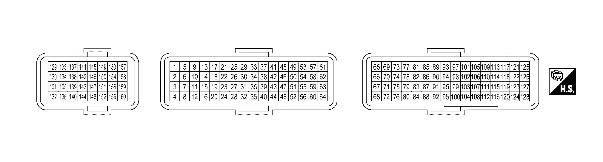
TERMINAL LAYOUT
PHYSICAL VALUES
NOTE:
-
Specification data are reference values and are measured between each terminal and ground.
-
Pulse signal is measured by CONSULT.
|
Terminal No. (Wire color) | Description | Condition |
Value (Approx.) | ||
|---|---|---|---|---|---|
| + | ŌłÆ | Signal name | Input/Output | ||
|
1 (Y) |
160 (B) |
Fuel injector driver power supply | Input |
[Engine is running]
|
Battery voltage (11 ŌĆō 14 V) |
|
2 (BR) |
160 (B) |
High pressure fuel pump (LO) | Output |
[Engine is running]
|
6.38 V |
|
[Engine is running]
|
7.63 V | ||||
|
3 (L) |
160 (B) |
Electric wastegate control actuator motor (+) | Output |
[Engine is running]
|
0 V |
|
[Engine is running]
|
0.69 V | ||||
|
4 (B) |
ŌĆö | Fuel injector driver ground | ŌĆö | ŌĆö | ŌĆö |
|
5 (G) |
160 (B) |
ECM power supply | Input | [Ignition switch: ON] |
Battery voltage (11 - 14 V) |
|
6 (SB) |
160 (B) |
Air fuel ratio (A/F) sensor 1 heater | Input |
[Engine is running]
|
Battery voltage (11 ŌĆō 14 V) |
|
7 (Y) |
160 (B) |
High pressure fuel pump (HI) | Output |
[Engine is running]
|
6.76 V |
|
[Engine is running]
|
7.97 V | ||||
|
8 (P) |
160 (B) |
Electric wastegate control actuator motor (-) | Output |
[Engine is running]
|
0 V |
|
[Engine is running]
|
0.9 V | ||||
|
9 (LG) |
160 (B) |
Fuel injector No. 1 (HI) | Output |
[Engine is running]
|
7.19 - 7.46 V |
|
11 (G) |
Fuel injector No. 2 (HI) | ||||
|
12 (BG) |
Fuel injector No. 3 (HI) | ||||
|
10 (L) |
160 (B) |
Crankcase ventilation valve | Output |
[Ignition switch: ON]
|
0V |
|
13 (L) |
14 (W) |
EGR volume control valve (+) | Output | [Ignition switch: ON] |
Battery voltage (11 - 14 V) |
|
[Engine is running]
|
1.71 V | ||||
|
14 (W) |
13 (L) |
EGR volume control valve (-) | Output | [Ignition switch: ON] |
Battery voltage (11 - 14 V) |
|
[Engine is running]
|
0.1 V | ||||
|
17 (Y) |
160 (B) |
Fuel injector No. 1 (LO) | Output |
[Engine is running]
|
7.18 - 7.35 V |
|
18 (BR) |
Fuel injector No. 3 (LO) | ||||
|
20 (R) |
Fuel injector No. 2 (LO) | ||||
|
21 (LG) |
ŌĆö | Lin | Input/ Output | ŌĆö | ŌĆö |
|
23 (L) |
ŌĆö | Lin | Input/ Output | ŌĆö | ŌĆö |
|
24 (LG) |
160 (B) |
ECM relay (Self shut-off) |
Input |
[Engine is running] [Ignition switch: OFF]
|
0.8 V |
| Output |
[Ignition switch: OFF]
|
0 V | |||
|
26 (B) |
160 (B) |
Turbocharger bypass control valve | Output |
[Engine is running]
|
14.28 V |
|
29 (P) |
160 (B) |
Fuel pump relay | Input |
[Ignition switch: ON]
|
0 V |
|
30 (GR) |
ŌĆö | Drivetrain CAN communication - H | Input/ Output | ŌĆö | ŌĆö |
|
31 (R) |
ŌĆö | Drivetrain CAN communication - L | Input/ Output | ŌĆö | ŌĆö |
|
32 (Y) |
160 (B) |
Charge air cooler electric water pump | Output |
[Engine is running]
|
0 - 13.0 V |
|
33 (Y) |
160 (B) |
Ignition signal No. 3 | Output |
[Engine is running]
|
0 - 13.0 V |
|
[Engine is running]
|
0 - 13.0 V | ||||
|
34 (R) |
160 (B) |
Charge air cooler coolant temperature sensor | Input | [Engine is running] |
0 - 4.8 V Output voltage varies with intake air temperature. |
|
36 (L) |
160 (B) |
Ignition signal No. 1 | Output |
[Engine is running]
|
0 - 13.0 V |
|
[Engine is running]
|
0 - 13.0 V | ||||
|
37 (LA/V) |
160 (B) |
Intake air temperature sensor 2 | Input |
[Engine is running]
|
2.37 V |
|
39 (P) |
160 (B) |
Charge air cooler electric water pump | Output |
[Engine is running]
|
0 - 14 V |
|
41 (LA/LG) |
ŌĆö |
Sensor ground (Fuel rail pressure sensor) |
ŌĆö | ŌĆö | ŌĆö |
|
44 (LG) |
160 (B) |
Ignition signal No. 2 | Output |
[Engine is running]
|
0 - 13.0 V |
|
[Engine is running]
|
0 - 13.0 V | ||||
|
45 (R) |
ŌĆö |
Sensor ground (Throttle position sensor 1 and 2) |
ŌĆö | ŌĆö | ŌĆö |
|
46 (B) |
ŌĆö | Shield | ŌĆö | ŌĆö | ŌĆö |
|
47 (BR) |
160 (B) |
Mass air flow sensor | Input |
[Ignition switch: ON]
|
4.16 V |
|
[Engine is running]
|
4.20 V | ||||
|
[Engine is running]
|
4.23 V | ||||
|
49 (W) |
160 (B) |
Knock sensor | Input |
[Engine is running]
|
2.48 V |
|
50 (B) |
ŌĆö |
Sensor ground (Mass air flow sensor and intake air temperature sensor) |
ŌĆö | ŌĆö | ŌĆö |
|
51 (LA/Y) |
160 (B) |
Admission valve | Input |
[Engine is running]
|
1.08 V |
|
52 (W) |
160 (B) |
Throttle position sensor 2 | Input |
[Engine is running]
|
4.47 V |
|
[Engine is running]
|
4.27 V | ||||
|
53 (GR) |
ŌĆĢ |
Sensor ground (Knock sensor) |
ŌĆĢ | ŌĆĢ | ŌĆĢ |
|
54 (B) |
ŌĆĢ | Shield | ŌĆĢ | ŌĆĢ | ŌĆĢ |
|
56 (L) |
160 (B) |
Air fuel ratio (A/F) sensor 1 | Input | [Ignition switch: ON] | 0.4 V |
|
57 (B) |
160 (B) |
Throttle position sensor 1 | Input |
[Engine is running]
|
0.62 V |
|
[Engine is running]
|
0.82 V | ||||
|
58 (LA/L) |
160 (B) |
Fuel rail pressure sensor | Input |
[Engine is running]
|
1.5 V |
|
[Engine is running]
|
3.0 V | ||||
|
60 (P) |
160 (B) |
Air fuel ratio (A/F) sensor 1 | Input |
[Engine is running]
|
0.3 - 0.5 V Output voltage varies with air fuel ratio. |
|
61 (LA/R) |
160 (B) |
Sensor power supply (Fuel rail pressure sensor) |
ŌĆö | [Ignition switch: ON] | 5 V |
|
62 (G) |
160 (B) |
Sensor power supply (Throttle position sensor 1 and 2) |
ŌĆö | [Ignition switch: ON] | 5 V |
|
64 (V) |
160 (B) |
Sensor power supply (Mass air flow sensor) |
ŌĆĢ | [Ignition switch: ON] | 5 V |
|
65 (Y) |
160 (B) |
Engine oil pressure control solenoid valve | Output |
[Engine is running]
|
1.78 V |
|
66 (BG) |
160 (B) |
Battery power supply | Input | [Ignition switch: ON] |
Battery voltage (11 - 14 V) |
|
67 (BG) |
160 (B) |
Throttle control motor (Open) | Output |
[Ignition switch: ON]
|
2.0 - 2.3 V |
|
68 (BR) |
160 (B) |
Throttle control motor (Close) | Output |
[Ignition switch: ON]
|
0 V |
|
70 (G) |
160 (B) |
Heated oxygen sensor 2 heater | Output |
[Engine is running]
|
ŌĆĢ |
|
[Ignition switch: ON]
[Engine is running]
|
Battery voltage (11 - 14 V) |
||||
|
71 (P) |
160 (B) |
Multi-way control valve (+) | Output |
[Engine is running]
|
0 V |
|
72 (W) |
160 (B) |
Multi-way control valve (-) | Output |
[Engine is running]
|
0 V |
|
74 (L) |
160 (B) |
Refrigerant pressure sensor | Input |
[Engine is running]
|
1.03 V |
|
75 (LA/Y) |
160 (B) |
Electric wastegate actuator | Input |
[Engine is running]
|
3.88 V |
|
77 (LA/R) |
103 (LA/W) |
Sensor power supply (Crankcase presser sensor and engine oil pressure sensor) |
ŌĆö | [Ignition switch: ON] | 5 V |
|
78 (LA/Y) |
160 (B) |
Sensor power supply (Crankshaft position sensor) |
ŌĆö | [Ignition switch: ON] | 5 V |
|
79 (W) |
105 (R) |
Sensor power supply (Refrigerant pressure sensor) |
ŌĆö | [Ignition switch: ON] | 5 V |
|
80 (LG) |
160 (B) |
Sensor power supply [Manifold absolute pressure (MAP) sensor and EGR differential pressure sensor] |
ŌĆö | [Ignition switch: ON] | 5 V |
|
81 (LA/L) |
160 (B) |
Turbocharger boost sensor | Input |
[Engine is running]
|
1.63 V |
|
[Engine is running]
|
1.58 V | ||||
|
82 (LA/SB) |
160 (B) |
Crankshaft position sensor 2 | Input |
[Engine is running]
The pulse cycle changes depending on rpm at idle. |
4.6 V |
|
[Engine is running]
|
4.6 V | ||||
|
83 (BR) |
160 (B) |
Sensor power supply (Multi-way control valve and electric wastegate control actuator) |
ŌĆö | [Ignition switch: ON] | 5 V |
|
84 (LA/W) |
160 (B) |
Sensor power supply (Turbocharger boost sensor and EGR volume control valve and admission valve) |
ŌĆö | [Ignition switch: ON] | 5 V |
|
86 (LA/G) |
100 (LA/B) |
Sensor power supply (Crankshaft position sensor 2 and intake camshaft position sensor) |
ŌĆö | [Ignition switch: ON] | 5 V |
|
87 (LG) |
160 (B) |
Engine coolant temperature sensor 2 | Input |
[Engine is running]
|
0.96 V |
|
88 (L) |
160 (B) |
Crankshaft position sensor (Electric intake valve timing control signal) |
Output |
[Engine is running]
|
4.83 V |
|
[Engine is running]
|
4.61 V | ||||
|
90 (LA/W) |
160 (B) |
Exhaust camshaft position sensor | Input |
[Engine is running]
|
4.41 V |
|
[Engine is running]
|
4.44 V | ||||
|
91 (LA/L) |
160 (B) |
Multi-way control valve | Input |
[Engine is running]
|
4.39 V |
|
92 (W) |
160 (B) |
Heated oxygen sensor 2 | Input |
[Engine is running]
|
3.8 - 1.0 V |
|
93 (LA/Y) |
160 (B) |
EGR differential pressure sensor | Input |
[Engine is running]
|
1.3 V |
|
94 (LA/R) |
160 (B) |
Sensor power supply (Exhaust camshaft position sensor) |
ŌĆĢ | [Ignition switch: ON] | 5 V |
|
95 (P) |
160 (B) |
Engine oil temperature sensor | Input |
[Engine is running]
|
0 - 4.8 V Output voltage varies with Engine oil temperature. |
|
96 (LA/R) |
160 (B) |
Crankshaft position sensor | Input |
[Engine is running]
|
4.93 V |
|
[Engine is running]
|
4.66 V | ||||
|
97 (B) |
ŌĆĢ |
Sensor ground (Heated oxygen sensor 2) |
ŌĆĢ | ŌĆĢ | ŌĆĢ |
|
99 (SB) |
ŌĆĢ |
Sensor ground (Exhaust gas temperature sensor) |
ŌĆĢ | ŌĆĢ | ŌĆĢ |
|
100 (LA/B) |
ŌĆö |
Sensor ground (Crankshaft position sensor 2 and intake camshaft position sensor) |
ŌĆö | ŌĆö | ŌĆö |
|
101 (L) |
160 (B) |
Engine coolant temperature sensor 1 | Input | [Engine is running] |
0 - 4.8 V Output voltage varies with Engine coolant temperature. |
|
102 (B) |
ŌĆĢ |
Sensor ground (Engine coolant temperature sensor 1, Engine coolant temperature sensor 2 and EGR temperature sensor) |
ŌĆĢ | ŌĆĢ | ŌĆĢ |
|
103 (LA/W) |
ŌĆĢ |
Sensor ground (Crankcase pressure sensor and engine oil pressure sensor) |
ŌĆö | ŌĆö | ŌĆö |
|
104 (BR) |
160 (B) |
EGR temperature sensor | Input | [Ignition switch: ON] | 4.29 V |
|
[Engine is running]
|
4.46 V | ||||
|
105 (R) |
ŌĆö |
Sensor ground (Refrigerant pressure sensor) |
ŌĆö | ŌĆö | ŌĆö |
|
106 (LA/L) |
ŌĆö |
Sensor ground [Manifold absolute pressure (MAP) sensor and EGR differencial pressure sensor] |
ŌĆö | ŌĆö | ŌĆö |
|
107 (LA/R) |
ŌĆĢ |
Sensor ground (Admission valve, turbocharger boost sensor, engine oil temperature sensor and EGR volume control valve) |
ŌĆĢ | ŌĆĢ | ŌĆĢ |
|
108 (LA/W) |
ŌĆö |
Sensor ground (Crankshaft position sensor) |
ŌĆö | ŌĆö | ŌĆö |
|
109 (LA/SB) |
100 (LA/B) |
Intake camshaft position sensor | Input |
[Engine is running]
|
4.31 - 4.43 V |
|
[Engine is running]
|
4.36 V | ||||
|
110 (LA/Y) |
ŌĆĢ |
Sensor ground (Exhaust camshaft position sensor) |
ŌĆĢ | ŌĆĢ | ŌĆĢ |
|
111 (LA/LG) |
ŌĆĢ | Sensor ground (Multi-way control valve, electric wastegate control actuator and intercooler temperature sensor) | ŌĆĢ | ŌĆĢ | ŌĆĢ |
|
112 (P) |
103 (LA/W) |
Crankcase pressure sensor | Input |
[Ignition switch: ON]
|
3.64V |
|
113 (BR) |
94 (LA/R) |
Exhaust gas temperature sensor | ŌĆĢ |
[Engine is running]
|
1.56 V |
|
114 (LA/V) |
160 (B) |
Engine oil pressure sensor | Input |
[Engine is running]
|
1.41 V |
|
[Engine is running]
|
1.74 V | ||||
|
116 (LA/G) |
107 (LA/R) |
EGR volume control valve | Input | [Ignition switch: ON] | 0.52 V |
|
[Engine is running]
|
0.57 V | ||||
|
117 (Y) |
160 (B) |
Exhaust valve timing intermediate lock control solenoid valve | Input |
[Engine is running]
|
Battery voltage (11 - 14 V) |
|
[Engine is running]
|
0.67 V | ||||
|
120 (LA/P) |
160 (B) |
Manifold absolute pressure (MAP) sensor | Input | [Ignition switch: ON] |
0.95 V Output voltage varies with atmospheric pressure. |
|
[Engine is running]
|
1.61 V | ||||
|
121 (G) |
160 (B) |
Admission valve motor (+) | Output | [Ignition switch: ON] |
Battery voltage (11 - 14 V) |
|
[Engine is running]
|
0.13 V | ||||
|
122 (R) |
160 (B) |
Admission valve motor (-) | Output | [Ignition switch: ON] |
Battery voltage (11 - 14 V) |
|
[Engine is running]
|
0.1 - 0.2 V | ||||
|
125 (L) |
160 (B) |
Exhaust valve timing control solenoid valve | Output |
[Engine is running]
|
Battery voltage (11 - 14 V) |
|
[Engine is running]
|
9.55 V | ||||
|
126 (BR) |
160 (B) |
EVAP canister purge volume control solenoid valve | Output |
[Engine is running]
|
Battery voltage (11 - 14 V) |
|
127 (W) |
160 (B) |
Intake camshaft position sensor (Electric intake valve timing control signal) | Input |
[Engine is running]
|
4.34 V |
|
[Engine is running]
|
4.45 V | ||||
|
129 (G) |
160 (B) |
EVAP control system pressure sensor | Input | [Ignition switch: ON] | 4.25 V |
|
131 (R) |
ŌĆö | Drivetrain CAN communication - L | Input/ Output | ŌĆö | ŌĆö |
|
132 (GR) |
ŌĆö | Drivetrain CAN communication - H | Input/ Output | ŌĆö | ŌĆö |
|
133 (LA/SB) |
160 (B) |
Sensor power supply (EVAP control system pressure sensor) |
ŌĆö | [Ignition switch: ON] | 5 V |
|
134 (LA/Y) |
160 (B) |
Engine speed signal | Output |
[Engine is running]
|
9.02 V |
|
136 (LA/BR) |
160 (B) |
Fuel tank temperature sensor | Input | [Engine is running] | 3.04 V |
|
138 (LA/G) |
160 (B) |
Fuel pump control module (FPCM) | Input/Output |
[Engine is running]
|
0.41 - 11.42 V |
|
141 (LG) |
160 (B) |
Ignition switch | Input | [Ignition switch: OFF] | 0 V |
| [Ignition switch: ON] |
Battery voltage (11 - 14 V) |
||||
|
142 (LA/V) |
143 (LA/BR) |
ASCD steering switch | Input |
[Ignition switch: ON]
|
4.22 V |
|
[Ignition switch: ON]
|
0 V | ||||
|
[Ignition switch: ON]
|
1.20 V | ||||
|
[Ignition switch: ON]
|
3.60 V | ||||
|
[Ignition switch: ON]
|
2.92 V | ||||
| ProPILOT Assist 1.1/2.1 steering switch | Input |
[Ignition switch: ON]
|
4.22 V | ||
|
[Ignition switch: ON]
|
0 V | ||||
|
[Ignition switch: ON]
|
1.20 V | ||||
|
[Ignition switch: ON]
|
2.15 V | ||||
|
[Ignition switch: ON]
|
2.92 V | ||||
|
[Ignition switch: ON]
|
3.60 V | ||||
|
143 (LA/BR) |
ŌĆö |
Sensor ground (ASCD/ProPILOT Assist 1.1/2.1 steering switch) |
ŌĆö | ŌĆö | ŌĆö |
|
144 (LA/L) |
160 (B) |
Fuel pump control module (FPCM) | Input/Output |
[Engine is running]
|
5.17 V |
|
145 (P) |
ŌĆö | Engine CAN communication - L | Input/ Output | ŌĆö | ŌĆö |
|
146 (GR) |
ŌĆö | Engine CAN communication - H | Input/ Output | ŌĆö | ŌĆö |
|
148 (GR) |
160 (B) |
Stop lamp switch | Input |
[Ignition switch: OFF]
|
0 V |
|
[Ignition switch: OFF]
|
Battery voltage (11 - 14 V) |
||||
|
149 (LA/V) |
160 (B) |
EVAP canister vent control valve | Output | [Ignition switch: ON] |
Battery voltage (11 - 14 V) |
|
150 (LA/P) |
152 (LA/Y) |
Sensor power supply (Accelerator pedal position sensor 2) |
ŌĆö | [Ignition switch: ON] | 5 V |
|
151 (LA/G) |
152 (LA/Y) |
Accelerator pedal position sensor 2 | Input |
[Ignition switch: ON]
|
2.27 V |
|
[Ignition switch: ON]
|
0.37 V | ||||
|
152 (LA/Y) |
ŌĆö |
Sensor ground (Accelerator pedal position sensor 2) |
ŌĆö | ŌĆö | ŌĆö |
|
153 (V) |
160 (B) |
Power supply for ECM | Input | [Ignition switch: ON] |
Battery voltage (11 - 14 V) |
|
154 (LG) |
159 (Y) |
Sensor power supply (Accelerator pedal position sensor 1) |
ŌĆö | [Ignition switch: ON] | 5 V |
|
155 (V) |
ŌĆö |
Sensor ground (Fuel tank temperature sensor and EVAP control system pressure sensor) |
ŌĆö | ŌĆö | ŌĆö |
|
156 (B) |
ŌĆö | ECM ground | ŌĆö | ŌĆö | ŌĆö |
|
157 (B) |
ŌĆö | ECM ground | ŌĆö | ŌĆö | ŌĆö |
|
158 (L) |
159 (Y) |
Accelerator pedal position sensor 1 | Input |
[Ignition switch: ON]
|
0.74 V |
|
[Ignition switch: ON]
|
4.53 V | ||||
|
159 (Y) |
ŌĆö |
Sensor ground (Accelerator pedal position sensor 1) |
ŌĆö | ŌĆö | ŌĆö |
|
160 (B) |
ŌĆö | ECM ground | ŌĆö | ŌĆö | ŌĆö |
Fail-safe
Refer to Fail-safe.
DTC Inspection Priority Chart
If some DTCs are displayed at the same time, perform inspections one by one based on the following priority chart.
| Priority | DTC | Detected items |
|---|---|---|
| 1 | B3A70, B3A71, B3A72, B3A73, B3A74, B3A75 | Battery current sensor |
| C0069, C0552 | G sensor | |
| C0500, C0501, C0502, C0503, C0505, C0506, C0507, C0508, C0509, C050B, C050C, C050D, C050E, C050F, C0511, C0512, C0513, C0514, C0515, C0517, C053C | Wheel speed sensor | |
| U0101, U0120, U012E, U0140, U0146, U0155, U0164, U0402, U0416, U0422, U042F, U0431, U0469, U10A0 | CAN communication line | |
| U0284, U1040 | Engine communication line | |
| U00AC, U02BB | LIN communication line | |
| U060F, U0644, U0652 | SENT communication line | |
| U1327, U2141, U214F, U2152, U2175, U2176 | MAC key | |
| U1CF8, U1CF9, U1CFA, U2118, U2141, U2148, U214A, U214E, U2150, U2153, U215B, U2175, U2176, U2241, U2248, U2252, U2259, U2276, U218B, U2212, U2384, U2385 | Network | |
| P0091, P0092 | Fuel rail pressure control system | |
| P0096, P0097, P0098 | Intake air temperature sensor 2 | |
| P00B3, P00B4 | Engine coolant temperature sensor 2 | |
| P00DE, P00E0, P00E1 | Charge air cooler coolant temperature sensor | |
| P0101, P0103, P00F2, P00F3, P00F4, P00F5 | Mass air flow sensor | |
| P0106 | Turbocharger boost sensor | |
| P0107, P0108, P2227 | Barometric pressure sensor | |
| P0111, P0112, P0113, P0127 | Intake air temperature sensor | |
| P0116, P0117, P0118, P0125 | Engine coolant temperature sensor | |
| P0122, P0123, P0222, P0223, P1225, P1226, P2135 | Throttle position sensor | |
| P0128 | Thermostat function | |
| P0181, P0182, P0183 | Fuel tank temperature sensor | |
| P0191, P0192, P0193, P119A, P119B, P119C, P119D, P119E | Fuel rail pressure sensor | |
| P0196, P0197, P0198 | Engine oil temperature sensor | |
| P026B, P02CC, P02CD, P02CE, P02CF, P02D0, P02D1, P02EE, P02EF, P02F0, P2B96 | Injection system | |
| P0326, P0327, P0328 | Knock sensor | |
| P0335, P2617, P2618, P2619 | Crankshaft position sensor | |
| P0340, P2614, P2615, P2616 | Camshaft position sensor | |
| P0365 | Exhaust valve timing position sensor | |
| P0385, P0386 | Crankshaft position sensor 2 | |
| P0401, P0402, P0404 | EGR volume control valve | |
| P0407, P0408, P046E, P0486 | EGR differential pressure sensor | |
| P040B, P040C, P040D ,P04FA, P1682 | EGR temperature sensor | |
| P044A, P044B, P044C, P044D, P044E | EGR volume control valve position sensor | |
| P0460, P0461, P0462, P0463 | Fuel level sensor | |
| P0500, P1526 | Nissan Ariya Vehicle speed sensor | |
| P051C, P051D, P053E | Crankcase pressure sensor | |
| P0520, P055F | Engine oil pressure sensor | |
| P0532,P0533 | Refrigerant pressure sensor | |
| P0560, P0561, P0562, P0A1E, P15B0, P15B1, P15B3 | Sub starter & generator | |
| P0604, P0605, P0606, P0607, P060A, P060B, P060C, P061B, P062B, P062D, P062F, P1603, P2610 | ECM | |
| P0641, P34C8 | Electric intake valve timing control module | |
| P06B0, P06B3, P06E6 | Sensor power supply | |
| P064D, P06DA, P06DB, P06DC | Engine oil pressure control solenoid valve | |
| P0719 | Brake pedal switch B | |
| P0850 | PNP switch | |
| P1096, P1097, P1098, P1099 | Humidity temperature sensor | |
| P1197 | Out of gas* | |
| P11A0, P11AA | VCR control | |
| P1536, P1538 | ASCD system | |
| P155B | Energy management control | |
| P155E, P155F | Sub starter & generator | |
| P1568 | Intelligent cruise control command value | |
| P161D, P161E, P161F | Immobilizer | |
| P2121, P2122, P2123, P2126, P2127, P2128, P2138, | Accelerator pedal position sensor | |
| P212B, P212C, P212D | Admission valve position sensor | |
| P2480, P2481, P2482, P2483, P2484 | Exhaust gas temperature sensor | |
| P2562, P2563, P2564, P2565, P2566 | Electric wastegate control valve position sensor | |
| P26A5, P26A6, P26A7 | Multi-way control valve position sensor | |
| P2DFD | EVAP system purge pump | |
| 2 | P0010 | Electric intake valve timing control module |
| P0030, P0031, P0032 | Air fuel ratio (A/F) sensor 1 heater | |
| P0046 | Electric wastegate control actuator | |
| P0036, P0037, P0038, P0053, P00D2 | Heated oxygen sensor 2 heater | |
| P0078, P0079, P0080 | Exhaust valve timing control solenoid valve | |
| P0090 | High pressure fuel pump | |
| P00C0, P00C1, P00C2 | Turbocharger bypass valve | |
| P0130, P0131, P0132, P014C, P014D, P015A, P015B, P2096, P2097, P2237, P2238, P2239, P2251, P2252, P2253, P2297 | Air fuel ratio (A/F) sensor 1 | |
| P0136, P0137, P0138, P0139, P2270, P2271, P2A01 | Heated oxygen sensor 2 | |
| P0235, P0237, P0238 | Turbocharger boost sensor | |
| P023A, P023B, P023C, P14A4, P14A5, P14A6, P14A7, P14A8, P14A9, P14AA, P14AC | Charge air cooler cooling electric water pump | |
| P0441 | EVAP control system purge flow monitoring | |
| P0443, P0444, P0445 | EVAP canister purge volume control solenoid valve | |
| P0446, P0447, P0448 | EVAP canister vent control valve | |
| P0450, P0451, P0452, P0453, P0454 | EVAP control system pressure sensor | |
| P04DB, P052E, P05D8, P05D9, P05DA, P2C91 | Crankcase ventilation valve | |
| P0531 | Refrigerant pressure sensor | |
| P1217 | Engine over temperature (OVERHEAT) | |
| P12A8, P3194 | Brake function | |
| P14C1, P1575, P1805 | Brake switch | |
| P11A2, P11A3, P11A4, P11AB, P11AC, P11AD, P11AE, P11AF | VCR control | |
| P2100, P2103 | Throttle control motor relay | |
| P2101 | Electric throttle control function | |
| P210B | Admission valve motor | |
| P26A3 | Multi-way control valve | |
| P34AC, P34AD, P34AE, P34AF | Electric intake valve timing control actuator | |
| 3 | P0011, P0012, P0016, P052A, P052B | Intake valve timing control |
| P0014, P0015, P0017, P054A, P054B | Exhaust valve timing control | |
| P0087, P0088 | Fuel pressure control | |
| P00FE | EVAP control system | |
| P0171, P0172 | Port fuel injection system function | |
| P01F0 | Coolant temperature | |
| P0201, P0202, P0203,P0261, P0262, P0264, P0265, P0267, P0268, P10C8, P10C9, P10CA | fuel injector | |
| P0234, P2263 | Turbocharger system | |
| P025A, P025B, P025C, P025D, P064A | Fuel pressure control | |
| P0300, P0301, P0302, P0303 | Misfire | |
| P0315 | Crankshaft position | |
| P0420 | Three way catalyst function | |
| P0456 | EVAP control system | |
| P04F1 | EVAP system purge line | |
| P0506, P0507 | Idle speed control | |
| P050A, P050B, P050E, P05EC, P2B95 | Cold start control | |
| P0522, P0523, P0524 | Engine oil pressure | |
| P0573 | Brake pedal switch A | |
| P059F, P159F | Active grille shutter | |
| P1148 | Closed loop control | |
| P11A1, P11A6, P11A7, P11A8, P11A9, P11B0, P11B1 | VCR control | |
| P1564 | ASCD/ProPILOT Assist steering switch | |
| P1572 | Brake pedal position switch | |
| P1574 | ASCD/ProPILOT Assist Nissan Ariya vehicle speed sensor | |
| P1A10 | ECM initial learning incomplete | |
| P2119 | Electric throttle control actuator | |
| P219A | Air fuel ratio (A/F) sensor 1 | |
| P268A | fuel injector calibration |
*: If ŌĆ£P1197ŌĆØis displayed with other DTC in priority 1, perform trouble diagnosis for ŌĆ£P1197ŌĆØ first.
DTC Index
├Ś:Applicable ŌĆö: Not applicable
| DTC *1 |
Items (CONSULT screen terms) | SRT code | Trip | MIL | Permanent DTC group *3 | Stop/ start indicator lamp *4 | Reference page | ||
|---|---|---|---|---|---|---|---|---|---|
| CONSULT | GST *2 | ||||||||
| B3A70 | 00 | B3A70 | IBS Battery Temp Sensor Failure (Open Circuit) | ŌĆĢ | 2 | ├Ś | A | ŌĆĢ | DTC Description |
| B3A71 | 00 | B3A71 | IBS Battery Current Sensor Failure (Open Circuit) | ŌĆĢ | 2 | ├Ś | A | ŌĆĢ | DTC Description |
| B3A72 | 00 | B3A72 | USM Voltage Measurement Failure (Open Circuit) | ŌĆĢ | 2 | ├Ś | A | ŌĆĢ | DTC Description |
| B3A73 | 00 | B3A73 | IBS temperature sensor Range/Performance (Mutual Comparison to Other Temperature Sensors) | ŌĆĢ | 2 | ├Ś | A | ŌĆĢ | DTC Description |
| B3A74 | 00 | B3A74 | IBS Battery Current Sensor Rationality Failure | ŌĆĢ | 2 | ├Ś | A | ŌĆĢ | DTC Description |
| B3A75 | 00 | B3A75 | USM Voltage Measurement Rationality Failure | ŌĆĢ | 2 | ├Ś | A | ŌĆĢ | DTC Description |
| C0069 | 00 | C0069 | Yaw Rate/Longitude Sensors | ŌĆĢ | 2 | ├Ś | A + B | ŌĆĢ | DTC Description |
| C0500 | 00 | C0500 | Left front wheel speed sensor | ŌĆĢ | 2 | ├Ś | A + B | ŌĆĢ | DTC Description |
| C0501 | 00 | C0501 | Left front wheel speed sensor | ŌĆĢ | 2 | ├Ś | A + B | ŌĆĢ | DTC Description |
| C0502 | 00 | C0502 | Left front wheel speed sensor | ŌĆĢ | 2 | ├Ś | A + B | ŌĆĢ | DTC Description |
| C0503 | 00 | C0503 | Left front wheel speed sensor | ŌĆĢ | 2 | ├Ś | A + B | ŌĆĢ | DTC Description |
| C0505 | 00 | C0505 | Left front wheel speed sensor | ŌĆĢ | 2 | ├Ś | A + B | ŌĆĢ | DTC Description |
| C0506 | 00 | C0506 | Right front wheel speed sensor | ŌĆĢ | 2 | ├Ś | A + B | ŌĆĢ | DTC Description |
| C0507 | 00 | C0507 | Right front wheel speed sensor | ŌĆĢ | 2 | ├Ś | A + B | ŌĆĢ | DTC Description |
| C0508 | 00 | C0508 | Right front wheel speed sensor | ŌĆĢ | 2 | ├Ś | A + B | ŌĆĢ | DTC Description |
| C0509 | 00 | C0509 | Right front wheel speed sensor | ŌĆĢ | 2 | ├Ś | A + B | ŌĆĢ | DTC Description |
| C050B | 00 | C050B | Right front wheel speed sensor | ŌĆĢ | 2 | ├Ś | A + B | ŌĆĢ | DTC Description |
| C050C | 00 | C050C | Left rear wheel speed sensor | ŌĆĢ | 2 | ├Ś | A + B | ŌĆĢ | DTC Description |
| C050D | 00 | C050D | Left rear wheel speed sensor | ŌĆĢ | 2 | ├Ś | A + B | ŌĆĢ | DTC Description |
| C050E | 00 | C050E | Left rear wheel speed sensor | ŌĆĢ | 2 | ├Ś | A + B | ŌĆĢ | DTC Description |
| C050F | 00 | C050F | Left rear wheel speed sensor | ŌĆĢ | 2 | ├Ś | A + B | ŌĆĢ | DTC Description |
| C0511 | 00 | C0511 | Left rear wheel speed sensor | ŌĆĢ | 2 | ├Ś | A + B | ŌĆĢ | DTC Description |
| C0512 | 00 | C0512 | Right rear wheel speed sensor | ŌĆĢ | 2 | ├Ś | A + B | ŌĆĢ | DTC Description |
| C0513 | 00 | C0513 | Right rear wheel speed sensor | ŌĆĢ | 2 | ├Ś | A + B | ŌĆĢ | DTC Description |
| C0514 | 00 | C0514 | Right rear wheel speed sensor | ŌĆĢ | 2 | ├Ś | A + B | ŌĆĢ | DTC Description |
| C0515 | 00 | C0515 | Right rear wheel speed sensor | ŌĆĢ | 2 | ├Ś | A + B | ŌĆĢ | DTC Description |
| C0517 | 00 | C0517 | Right rear wheel speed sensor | ŌĆĢ | 2 | ├Ś | A + B | ŌĆĢ | DTC Description |
| C053C | 00 | C053C | Wheel speed sensor | ŌĆĢ | 2 | ├Ś | A + B | ŌĆĢ | DTC Description |
| C0552 | 00 | C0552 | Longitudinal Acceleration Sensor Range/Performance | ŌĆĢ | 2 | ├Ś | A + B | ŌĆĢ | DTC Description |
| U00AC | 00 | U00AC | USM-IBS LIN Communication Failure | ŌĆĢ | 2 | ├Ś | A | ŌĆĢ | DTC Description |
| U0101 | 00 | U0101 | Lost communication (TCM) | ŌĆĢ | 2 | ├Ś | A + B | ├Ś | DTC Description |
| U0120 | 00 | U0120 | Starter/generator control module | ŌĆĢ | 2 | ├Ś | A + B | ├Ś | DTC Description |
| U012E | 00 | U012E | Lost communication (camshaft position control module) | ŌĆĢ | 2 | ├Ś | A + B | ŌĆĢ | DTC Description |
| U0131 | 00 | U0131 | Lost communication (EPS C/U) | ŌĆĢ | 2 | ├Ś | A + B | ├Ś | DTC Description |
| U0140 | 00 | U0140 | Lost communication with body control module | ŌĆĢ | 2 | ├Ś | A + B | ├Ś | DTC Description |
| U0146 | 00 | U0146 | Lost communication with gateway A | ŌĆĢ | 2 | ├Ś | A + B | ŌĆĢ | DTC Description |
| U0155 | 00 | U0155 | Lost communication with instrument panel cluster (IPC) control module | ŌĆĢ | 2 | ├Ś | A + B | ŌĆĢ | DTC Description |
| U0164 | 00 | U0164 | Lost communication with HVAC control module | ŌĆĢ | 2 | ├Ś | A + B | ŌĆĢ | DTC Description |
| U0284 | 00 | U0284 | Lost communication with active grille air shutter module A | ŌĆĢ | 2 | ├Ś | A + B | ŌĆĢ | DTC Description |
| U02BB | 00 | U02BB | Lost communication with EVAP system purge pump | ŌĆĢ | 2 | ├Ś | A + B | ŌĆĢ | DTC Description |
| U0402 | 00 | U0402 | Invalid data (TCM) | ŌĆĢ | 2 | ├Ś | A + B | ├Ś | DTC Description |
| U0416 | 00 | U0416 | Invalid data (ABS C/U) | ŌĆĢ | 2 | ├Ś | A + B | ├Ś | DTC Description |
| U0422 | 00 | U0422 | Invalid data (BCM) | ŌĆĢ | 2 | ├Ś | A + B | ├Ś | DTC Description |
| U042F | 00 | U042F | Invalid data (camshaft position control module) | ŌĆĢ | 2 | ├Ś | A + B | ŌĆĢ | DTC Description |
| U0431 | 00 | U0431 | Invalid data (BCM A) | ŌĆĢ | 2 | ├Ś | A + B | ├Ś | DTC Description |
| U0469 | 00 | U0469 | Invalid data (starter/generator control module) | ŌĆĢ | 2 | ├Ś | A + B | ├Ś | DTC Description |
| U060F | 00 | U060F | Lost communication with mass or volume air flow sensor A | ŌĆĢ | 1 or 2 | ├Ś | A + B | ŌĆĢ | DTC Description |
| U0644 | 00 | U0644 | Lost communication with wastegate position sensor A | ŌĆĢ | 2 | ├Ś | A + B | ŌĆĢ | DTC Description |
| U0652 | 00 | U0652 | Lost communication (EGR sensor B) | ŌĆĢ | 2 | ├Ś | A + B | ŌĆĢ | DTC Description |
| U1040 | 00 | U1040 | Engine communication | ŌĆĢ | 2 | ŌĆĢ | ŌĆĢ | ├Ś | DTC Description |
| U10A0 | 00 | U10A0 | Lost communication (VCR) | ŌĆĢ | 2 | ├Ś | A + B | ŌĆĢ | DTC Description |
| U1327 | 52 | U1327 | MAC Key update | ŌĆĢ | 1 | ŌĆĢ | ŌĆĢ | ŌĆĢ | DTC Description |
| 54 | U1327 | MAC Key update | ŌĆĢ | 1 | ŌĆĢ | ŌĆĢ | ŌĆĢ | ||
| U1CF8 | 00 | U1CF8 | Lost communication with ECM in secondary ECU | ŌĆĢ | 2 | ├Ś | B | ŌĆĢ | DTC Description |
| U1CF9 | 00 | U1CF9 | Lost communication with VDC in secondary ECU | ŌĆĢ | 2 | ├Ś | A + B | ├Ś | DTC Description |
| U1CFA | 00 | U1CFA | Lost communication with USM in secondary ECU | ŌĆĢ | 2 | ├Ś | A + B | ├Ś | DTC Description |
| U2118 | 87 | U2118 | CAN comm err (Intelligent Key) | ŌĆĢ | 2 | ŌĆĢ | ŌĆĢ | ŌĆĢ | DTC Description |
| U2141 | 57 | U2141 | CAN comm err (TCM) | ŌĆĢ | 2 | ŌĆĢ | ŌĆĢ | ŌĆĢ | DTC Description |
| 87 | U2141 | CAN comm err (TCM) | ŌĆĢ | 2 | ŌĆĢ | ŌĆĢ | ŌĆĢ | ||
| U2148 | 83 | U2148 | CAN comm err (brake control unit) | ŌĆĢ | 2 | ŌĆĢ | ŌĆĢ | ŌĆĢ | DTC Description |
| 87 | U2148 | CAN comm err (brake control unit) | ŌĆĢ | 2 | ŌĆĢ | ŌĆĢ | ŌĆĢ | ||
| U214A | 83 | U214A | CAN comm err (AWD/4WD) | ŌĆĢ | 2 | ŌĆĢ | ŌĆĢ | ŌĆĢ | DTC Description |
| 87 | U214A | CAN comm err (AWD/4WD) | ŌĆĢ | 2 | ŌĆĢ | ŌĆĢ | ŌĆĢ | ||
| U214E | 87 | U214E | CAN comm err (combination meter) | ŌĆĢ | 2 | ŌĆĢ | ŌĆĢ | ŌĆĢ | DTC Description |
| U214F | 57 | U214F | CAN comm err (BCM) | ŌĆĢ | 1 | ŌĆĢ | ŌĆĢ | ŌĆĢ | DTC Description |
| 83 | U214F | CAN comm err (BCM) | ŌĆĢ | 2 | ŌĆĢ | ŌĆĢ | ŌĆĢ | ||
| 87 | U214F | CAN comm err (BCM) | ŌĆĢ | 2 | ŌĆĢ | ŌĆĢ | ŌĆĢ | ||
| U2150 | 83 | U2150 | CAN comm err (AIRBAG) | ŌĆĢ | 2 | ŌĆĢ | ŌĆĢ | ŌĆĢ | DTC Description |
| 87 | U2150 | CAN comm err (AIRBAG) | ŌĆĢ | 2 | ŌĆĢ | ŌĆĢ | ŌĆĢ | ||
| U2152 | 57 | U2152 | CAN comm err (ADAS control unit) | ŌĆĢ | 1 | ŌĆĢ | ŌĆĢ | ŌĆĢ | DTC Description |
| 83 | U2152 | CAN comm err (ADAS control unit) | ŌĆĢ | 2 | ŌĆĢ | ŌĆĢ | ŌĆĢ | ||
| 87 | U2152 | CAN comm err (ADAS control unit) | ŌĆĢ | 2 | ŌĆĢ | ŌĆĢ | ŌĆĢ | ||
| U2153 | 87 | U2153 | CAN comm err (HVAC) ch1 | ŌĆĢ | 2 | ŌĆĢ | ŌĆĢ | ŌĆĢ | DTC Description |
| U215B | 83 | U215B | CAN comm err (IPDM E/R) | ŌĆĢ | 2 | ŌĆĢ | ŌĆĢ | ŌĆĢ | DTC Description |
| 87 | U215B | CAN comm err (IPDM E/R) | ŌĆĢ | 2 | ŌĆĢ | ŌĆĢ | ŌĆĢ | ||
| U2175 | 57 | U2175 | CAN comm err (AVM) | ŌĆĢ | 1 | ŌĆĢ | ŌĆĢ | ŌĆĢ | DTC Description |
| 87 | U2175 | CAN comm err (AVM) | ŌĆĢ | 1 | ŌĆĢ | ŌĆĢ | ŌĆĢ | ||
| U2176 | 57 | U2176 | CAN comm err (CCM) | ŌĆĢ | 1 | ŌĆĢ | ŌĆĢ | ŌĆĢ | DTC Description |
| 87 | U2176 | CAN comm err (CCM) | ŌĆĢ | 1 | ŌĆĢ | ŌĆĢ | ŌĆĢ | ||
| U218B | 83 | U218B | CAN communication error | ŌĆĢ | 2 | ŌĆĢ | ŌĆĢ | ŌĆĢ | DTC Description |
| 87 | U218B | CAN communication error | ŌĆĢ | 2 | ŌĆĢ | ŌĆĢ | ŌĆĢ | ||
| U2212 | 87 | U2212 | CAN communication error brake unit | ŌĆĢ | 2 | ŌĆĢ | ŌĆĢ | ŌĆĢ | DTC Description |
| U2241 | 83 | U2241 | CAN comm err (TCM) | ŌĆĢ | 2 | ŌĆĢ | ŌĆĢ | ŌĆĢ | DTC Description |
| 87 | U2241 | CAN comm err (TCM) | ŌĆĢ | 2 | ŌĆĢ | ŌĆĢ | ŌĆĢ | ||
| U2248 | 83 | U2248 | CAN comm err (brake control unit) | ŌĆĢ | 2 | ŌĆĢ | ŌĆĢ | ŌĆĢ | DTC Description |
| 87 | U2248 | CAN comm err (brake control unit) | ŌĆĢ | 2 | ŌĆĢ | ŌĆĢ | ŌĆĢ | ||
| U2252 | 83 | U2252 | CAN comm err (ADAS control unit) | ŌĆĢ | 2 | ŌĆĢ | ŌĆĢ | ŌĆĢ | DTC Description |
| 87 | U2252 | CAN comm err (ADAS control unit) | ŌĆĢ | 2 | ŌĆĢ | ŌĆĢ | ŌĆĢ | ||
| U2259 | 87 | U2259 | CAN comm err (steering control unit) | ŌĆĢ | 2 | ŌĆĢ | ŌĆĢ | ŌĆĢ | DTC Description |
| U2276 | 83 | U2276 | CAN comm err (CCM) | ŌĆĢ | 2 | ŌĆĢ | ŌĆĢ | ŌĆĢ | DTC Description |
| 87 | U2276 | CAN comm err (CCM) | ŌĆĢ | 2 | ŌĆĢ | ŌĆĢ | ŌĆĢ | ||
| U2384 | 83 | U2384 | CAN comm err (eVTC) | ŌĆĢ | 2 | ŌĆĢ | ŌĆĢ | ŌĆĢ | DTC Description |
| 87 | U2384 | CAN comm err (eVTC) | ŌĆĢ | 2 | ŌĆĢ | ŌĆĢ | ŌĆĢ | ||
| U2385 | 87 | U2385 | CAN communication error (VCR) | ŌĆĢ | 2 | ŌĆĢ | ŌĆĢ | ŌĆĢ | DTC Description |
| P0010 | 00 | P0010 | A camshaft position actuator B1 | ŌĆĢ | 2 | ├Ś | A + B | ├Ś | DTC Description |
| P0011 | 00 | P0011 | A camshaft position bank 1 | ├Ś | 2 | ├Ś | A | ├Ś | DTC Description |
| P0012 | 00 | P0012 | A camshaft position bank 1 | ├Ś | 2 | ├Ś | A | ŌĆĢ | DTC Description |
| P0014 | 00 | P0014 | B camshaft position bank 1 | ├Ś | 2 | ├Ś | A | ├Ś | DTC Description |
| P0015 | 00 | P0015 | B camshaft position bank 1 | ├Ś | 2 | ├Ś | A | ŌĆĢ | DTC Description |
| P0016 | 00 | P0016 | Crankshaft position B1 sensor A | ŌĆĢ | 2 | ├Ś | A + B | ŌĆĢ | DTC Description |
| P0017 | 00 | P0017 | Crankshaft position B1 sensor B | ŌĆĢ | 2 | ├Ś | A + B | ŌĆĢ | DTC Description |
| P0030 | 00 | P0030 | Heated oxygen sensor heater 1 bank 1 | ŌĆö | 2 | ├Ś | A + B | ŌĆĢ | DTC Description |
| P0031 | 00 | P0031 | Heated oxygen sensor heater 1 bank 1 | ŌĆĢ | 2 | ├Ś | A + B | ŌĆĢ | DTC Description |
| P0032 | 00 | P0032 | Heated oxygen sensor heater 1 bank 1 | ŌĆĢ | 2 | ├Ś | A + B | ŌĆĢ | DTC Description |
| P0036 | 00 | P0036 | Heated oxygen sensor heater 2 bank 1 | ŌĆĢ | 2 | ├Ś | A + B | ├Ś | DTC Description |
| P0037 | 00 | P0037 | Heated oxygen sensor heater 2 bank 1 | ŌĆĢ | 2 | ├Ś | A + B | ├Ś | DTC Description |
| P0038 | 00 | P0038 | Heated oxygen sensor heater 2 bank 1 | ŌĆĢ | 2 | ├Ś | A + B | ├Ś | DTC Description |
| P0046 | 00 | P0046 | Turbocharger/supercharger boost control A | ŌĆĢ | 2 | ├Ś | A + B | ŌĆĢ | DTC Description |
| P0053 | 00 | P0053 | Heated oxygen sensor 1 heater bank 1 | ├Ś*4 | 2 | ├Ś | A + B | ŌĆĢ | DTC Description |
| P0078 | 00 | P0078 | Exhaust valve control solenoid bank 1 | ŌĆĢ | 2 | ├Ś | A + B | ├Ś | DTC Description |
| P0079 | 00 | P0079 | Exhaust valve control solenoid | ŌĆĢ | 2 | ├Ś | A + B | ├Ś | DTC Description |
| P0080 | 00 | P0080 | Exhaust valve control solenoid | ŌĆĢ | 2 | ├Ś | A + B | ├Ś | DTC Description |
| P0087 | 00 | P0087 | Fuel rail/system pressure bank1 | ŌĆĢ | 2 | ├Ś | A + B | ├Ś | DTC Description |
| P0088 | 00 | P0088 | Fuel rail/system pressure bank1 | ŌĆĢ | 2 | ├Ś | A + B | ├Ś | DTC Description |
| P0090 | 00 | P0090 | Fuel pressure regulator A control | ŌĆĢ | 2 | ├Ś | A + B | ├Ś | DTC Description |
| P0091 | 00 | P0091 | Fuel pressure regulator 1 | ŌĆĢ | 2 | ├Ś | A + B | ├Ś | DTC Description |
| P0092 | 00 | P0092 | Fuel pressure regulator 1 | ŌĆĢ | 2 | ├Ś | A + B | ├Ś | DTC Description |
| P0096 | 00 | P0096 | Intake air temperature sensor 2 bank 1 | ŌĆĢ | 2 | ├Ś | A + B | ŌĆĢ | DTC Description |
| P0097 | 00 | P0097 | Intake air temperature sensor 2 bank 1 | ŌĆĢ | 2 | ├Ś | A + B | ŌĆĢ | DTC Description |
| P0098 | 00 | P0098 | Intake air temperature sensor 2 bank 1 | ŌĆĢ | 2 | ├Ś | A + B | ŌĆĢ | DTC Description |
| P00B3 | 00 | P00B3 | Radiator coolant temperature sensor | ŌĆĢ | 2 | ŌĆĢ | ŌĆĢ | ŌĆĢ | DTC Description |
| P00B4 | 00 | P00B4 | Radiator coolant temperature sensor | ŌĆĢ | 2 | ŌĆĢ | ŌĆĢ | ŌĆĢ | DTC Description |
| P00C0 | 00 | P00C0 | Turbo/supercharger bypass valve B | ŌĆĢ | 2 | ├Ś | A + B | ŌĆĢ | DTC Description |
| P00C1 | 00 | P00C1 | Turbocharger/supercharger bypass valve B | ŌĆĢ | 2 | ├Ś | A + B | ŌĆĢ | DTC Description |
| P00C2 | 00 | P00C2 | Turbocharger/supercharger bypass valve B | ŌĆĢ | 2 | ├Ś | A + B | ŌĆĢ | DTC Description |
| P00D2 | 00 | P00D2 | Heated O2 sensor heater B1 sensor 2 | ├Ś | 2 | ├Ś | A + B | ŌĆĢ | DTC Description |
| P00DE | 00 | P00DE | Charge air cooler coolant temp sensor | ŌĆĢ | 2 | ├Ś | A + B | ŌĆĢ | DTC Description |
| P00E0 | 00 | P00E0 | Charge air cooler coolant temp | ŌĆĢ | 2 | ├Ś | A + B | ŌĆĢ | DTC Description |
| P00E1 | 00 | P00E1 | Charge air cooler coolant temp | ŌĆĢ | 2 | ├Ś | A + B | ŌĆĢ | DTC Description |
| P00F2 | 00 | P00F2 | Humidity sensor | ŌĆĢ | 2 | ├Ś | A + B | ŌĆĢ | DTC Description |
| P00F3 | 00 | P00F3 | Humidity sensor | ŌĆĢ | 2 | ├Ś | A + B | ŌĆĢ | DTC Description |
| P00F4 | 00 | P00F4 | Humidity sensor | ŌĆĢ | 2 | ├Ś | A + B | ŌĆĢ | DTC Description |
| P00F5 | 00 | P00F5 | Humidity sensor | ŌĆĢ | 2 | ├Ś | A + B | ŌĆĢ | DTC Description |
| P00FE | 00 | P00FE | EVAP system vapor line | ├Ś | 2 | ├Ś | A + B | ŌĆĢ | DTC Description |
| P0101 | 00 | P0101 | MAF SEN/CIRCUIT-B1 | ŌĆĢ | 1 or 2 | ├Ś or ŌĆĢ | A + B or ŌĆĢ | ├Ś | DTC Description |
| P0103 | 00 | P0103 | MAF SEN/CIRCUIT-B1 | ŌĆĢ | 1 | ├Ś | A + B | ├Ś | DTC Description |
| P0106 | 00 | P0106 | Manifold absolute pressure/Barometric pressure sensor | ŌĆĢ | 2 | ├Ś | A + B | ŌĆĢ | DTC Description |
| P0107 | 00 | P0107 | Absolute pressure sensor | ŌĆĢ | 2 | ├Ś | A + B | ŌĆĢ | DTC Description |
| P0108 | 00 | P0108 | Mass or volume air flow sensor B | ŌĆĢ | 2 | ├Ś | A + B | ŌĆĢ | DTC Description |
| P0111 | 00 | P0111 | Intake air temperature sensor 1 bank 1 | ŌĆĢ | 2 | ├Ś | A + B | ŌĆĢ | DTC Description |
| P0112 | 00 | P0112 | Intake air temperature sensor bank 1 | ŌĆĢ | 2 | ├Ś | A + B | ├Ś | DTC Description |
| P0113 | 00 | P0113 | Intake air temperature sensor bank 1 | ŌĆĢ | 2 | ├Ś | A + B | ├Ś | DTC Description |
| P0116 | 00 | P0116 | Engine coolant temperature sensor 1 | ŌĆĢ | 2 | ├Ś | A + B | DTC Description | |
| P0117 | 00 | P0117 | Engine coolant temperature sensor 1 | ŌĆĢ | 1 or 2 | ├Ś | A + B | ├Ś | DTC Description |
| P0118 | 00 | P0118 | Engine coolant temperature sensor 1 | ŌĆĢ | 1 or 2 | ├Ś | A + B | ├Ś | DTC Description |
| P0122 | 00 | P0122 | Throttle position sensor A | ŌĆĢ | 1 | ├Ś | A + B | ŌĆĢ | DTC Description |
| P0123 | 00 | P0123 | Throttle position sensor A | ŌĆĢ | 1 | ├Ś | A + B | ŌĆĢ | DTC Description |
| P0125 | 00 | P0125 | Engine coolant temperature sensor 1 | ŌĆĢ | 2 | ├Ś | A + B | ŌĆĢ | DTC Description |
| P0127 | 00 | P0127 | Intake air temperature | ŌĆĢ | 2 | ├Ś | A + B | ŌĆĢ | DTC Description |
| P0128 | 00 | P0128 | Coolant thermostat | ŌĆĢ | 2 | ├Ś | A + B | ŌĆĢ | DTC Description |
| P0130 | 00 | P0130 | Heated oxygen sensor 1 bank 1 | ├Ś | 2 | ├Ś | A + B | ŌĆĢ | DTC Description |
| P0131 | 00 | P0131 | Heated oxygen sensor 1 bank 1 | ├Ś | 2 | ├Ś | A + B | ŌĆĢ | DTC Description |
| P0132 | 00 | P0132 | Heated oxygen sensor 1 bank 1 | ├Ś | 2 | ├Ś | A + B | ŌĆĢ | DTC Description |
| P0136 | 00 | P0136 | Heater oxygen sensor 2 (bank 1) | ├Ś | 2 | ├Ś | A + B | ŌĆĢ | DTC Description |
| P0137 | 00 | P0137 | Heater oxygen sensor 2 (bank 1) | ├Ś | 2 | ├Ś | A + B | ŌĆĢ | DTC Description |
| P0138 | 00 | P0138 | Heater oxygen sensor 2 (bank 1) | ├Ś | 2 | ├Ś | A + B | ŌĆĢ | DTC Description |
| P0139 | 00 | P0139 | Heater oxygen sensor 2 (bank 1) | ├Ś | 2 | ├Ś | A + B or A | ŌĆĢ | DTC Description |
| P014C | 00 | P014C | Heated oxygen sensor 1 bank 1 | ├Ś | 2 | ├Ś | A | ŌĆĢ | DTC Description |
| P014D | 00 | P014D | Heated oxygen sensor 1 bank 1 | ├Ś | 2 | ├Ś | A | ŌĆĢ | DTC Description |
| P015A | 00 | P015A | Heated oxygen sensor 1 bank 1 | ├Ś | 2 | ├Ś | A | ŌĆĢ | DTC Description |
| P015B | 00 | P015B | Heated oxygen sensor 1 bank 1 | ├Ś | 2 | ├Ś | A | ŌĆĢ | DTC Description |
| P0171 | 00 | P0171 | Fuel system too lean bank 1 | ├Ś | 2 | ├Ś | A + B | ├Ś | DTC Description |
| P0172 | 00 | P0172 | Fuel system too rich bank 1 | ├Ś | 2 | ├Ś | A + B | ├Ś | DTC Description |
| P0181 | 00 | P0181 | Fuel temperature sensor A | ŌĆĢ | 2 | ├Ś | A + B | ŌĆĢ | DTC Description |
| P0182 | 00 | P0182 | Fuel temperature sensor A | ŌĆĢ | 2 | ├Ś | A + B | ŌĆĢ | DTC Description |
| P0183 | 00 | P0183 | Fuel temperature sensor A | ŌĆĢ | 2 | ├Ś | A + B | ŌĆĢ | DTC Description |
| P0191 | 00 | P0191 | Fuel rail pressure sensor bank 1 | ŌĆĢ | 2 | ├Ś | A + B | ŌĆĢ | DTC Description |
| P0192 | 00 | P0192 | Fuel rail pressure sensor bank 1 | ŌĆĢ | 2 | ├Ś | A + B | ├Ś | DTC Description |
| P0193 | 00 | P0193 | Fuel rail pressure sensor bank 1 | ŌĆĢ | 2 | ├Ś | A + B | ├Ś | DTC Description |
| P0196 | 00 | P0196 | Engine oil temperature sensor A | ŌĆĢ | 2 | ├Ś | A + B | ŌĆĢ | DTC Description |
| P0197 | 00 | P0197 | Engine oil temperature sensor A | ŌĆĢ | 2 | ├Ś | A + B | ŌĆĢ | DTC Description |
| P0198 | 00 | P0198 | Engine oil temperature sensor A | ŌĆĢ | 2 | ├Ś | A + B | ŌĆĢ | DTC Description |
| P01F0 | 00 | P01F0 | Coolant temperature | ŌĆĢ | 2 | ├Ś | A + B | ŌĆĢ | DTC Description |
| P0201 | 00 | P0201 | Cylinder 1 injector A | ŌĆĢ | 2 | ├Ś | A + B | ├Ś | DTC Description |
| P0202 | 00 | P0202 | Cylinder 2 injector A | ŌĆĢ | 2 | ├Ś | A + B | ├Ś | DTC Description |
| P0203 | 00 | P0203 | Cylinder 3 injector A | ŌĆĢ | 2 | ├Ś | A + B | ŌĆĢ | DTC Description |
| P0222 | 00 | P0222 | Throttle position sensor B | ŌĆĢ | 1 | ├Ś | A + B | ŌĆĢ | DTC Description |
| P0223 | 00 | P0223 | Throttle position sensor B | ŌĆĢ | 1 | ├Ś | A + B | ŌĆĢ | DTC Description |
| P0234 | 00 | P0234 | Turbocharger/supercharger A overboost condition | ŌĆĢ | 1 | ├Ś | A + B | ŌĆĢ | DTC Description |
| P0235 | 00 | P0235 | Turbocharger/supercharger boost sensor A | ŌĆĢ | 2 | ├Ś | A + B | ŌĆĢ | DTC Description |
| P0237 | 00 | P0237 | Turbocharger/supercharger boost sensor A | ŌĆĢ | 2 | ├Ś | A + B | ŌĆĢ | DTC Description |
| P0238 | 00 | P0238 | Turbocharger/supercharger boost sensor A | ŌĆĢ | 2 | ├Ś | A + B | ŌĆĢ | DTC Description |
| P023A | 00 | P023A | Charge air cooler coolant pump | ŌĆĢ | 2 | ├Ś | A + B | ŌĆĢ | DTC Description |
| P023B | 00 | P023B | Charge air cooler coolant pump | ŌĆĢ | 2 | ├Ś | A + B | ŌĆĢ | DTC Description |
| P023C | 00 | P023C | Charge air cooler coolant pump | ŌĆĢ | 2 | ├Ś | A + B | ŌĆĢ | DTC Description |
| P025A | 00 | P025A | Fuel pump module A control | ŌĆĢ | 2 | ├Ś | A + B | ŌĆĢ | DTC Description |
| P025B | 00 | P025B | Fuel pump module A | ŌĆĢ | 1 or 2 | ├Ś | A + B | ŌĆĢ | DTC Description |
| P025C | 00 | P025C | Fuel pump module A | ŌĆĢ | 2 | ├Ś | A + B | ŌĆĢ | DTC Description |
| P025D | 00 | P025D | Fuel pump module A | ŌĆĢ | 2 | ├Ś | A + B | ŌĆĢ | DTC Description |
| P0261 | 00 | P0261 | Cylinder 1 injector A | ŌĆĢ | 2 | ├Ś | A + B | ├Ś | DTC Description |
| P0262 | 00 | P0262 | Cylinder 1 injector A | ŌĆĢ | 2 | ├Ś | A + B | ├Ś | DTC Description |
| P0264 | 00 | P0264 | Cylinder 2 injector A | ŌĆĢ | 2 | ├Ś | A + B | ├Ś | DTC Description |
| P0265 | 00 | P0265 | Cylinder 2 injector A | ŌĆĢ | 2 | ├Ś | A + B | ├Ś | DTC Description |
| P0267 | 00 | P0267 | Cylinder 3 injector A | ŌĆĢ | 2 | ├Ś | A + B | ├Ś | DTC Description |
| P0268 | 00 | P0268 | Cylinder 3 injector A | ŌĆĢ | 2 | ├Ś | A + B | ├Ś | DTC Description |
| P026B | 00 | P026B | Injection timing | ŌĆĢ | 2 | ├Ś | A + B | ŌĆĢ | DTC Description |
| P02CC | 00 | P02CC | Cylinder 1 fuel injector A offset learning at min limit | ŌĆĢ | 2 | ├Ś | A + B | ├Ś | DTC Description |
| P02CD | 00 | P02CD | Cylinder 1 fuel injector A offset learning at max limit | ŌĆĢ | 2 | ├Ś | A + B | ├Ś | DTC Description |
| P02CE | 00 | P02CE | Cylinder 2 fuel injector A offset learning at min limi | ŌĆĢ | 2 | ├Ś | A + B | ├Ś | DTC Description |
| P02CF | 00 | P02CF | Cylinder 2 fuel injector A offset learning at max limit | ŌĆĢ | 2 | ├Ś | A + B | ├Ś | DTC Description |
| P02D0 | 00 | P02D0 | Cylinder 3 fuel injector A offset learning at min limit | ŌĆĢ | 2 | ├Ś | A + B | ├Ś | DTC Description |
| P02D1 | 00 | P02D1 | Cylinder 3 fuel injector A offset learning at max limit | ŌĆĢ | 2 | ├Ś | A + B | ├Ś | DTC Description |
| P02EE | 00 | P02EE | Cylinder 1 injector | ŌĆĢ | 2 | ├Ś | A + B | ├Ś | DTC Description |
| P02EF | 00 | P02EF | Cylinder 2 injector | ŌĆĢ | 2 | ├Ś | A + B | ├Ś | DTC Description |
| P02F0 | 00 | P02F0 | Cylinder 3 injector | ŌĆĢ | 2 | ├Ś | A + B | ├Ś | DTC Description |
| P0300 | 00 | P0300 | Multiple cylinder misfire | ├Ś | 2 | ├Ś | A + B | ├Ś | DTC Description |
| P0301 | 00 | P0301 | Cylinder 1 misfire | ├Ś | 2 | ├Ś | A + B | ├Ś | DTC Description |
| P0302 | 00 | P0302 | Cylinder 2 misfire | ├Ś | 2 | ├Ś | A + B | ├Ś | DTC Description |
| P0303 | 00 | P0303 | Cylinder 3 misfire | ├Ś | 2 | ├Ś | A + B | ├Ś | DTC Description |
| P0315 | 00 | P0315 | Crankshaft position | ŌĆĢ | 2 | ├Ś | A + B | ŌĆĢ | DTC Description |
| P0326 | 00 | P0326 | Knock/combustion vibration sensor 1 (bank 1) | ŌĆĢ | 2 | ├Ś | A + B | ŌĆĢ | DTC Description |
| P0327 | 00 | P0327 | Knock sensor 1 bank 1 | ŌĆĢ | 2 | ├Ś | A + B | ŌĆĢ | DTC Description |
| P0328 | 00 | P0328 | Knock sensor 1 bank 1 | ŌĆĢ | 2 | ├Ś | A + B | ŌĆĢ | DTC Description |
| P0335 | 00 | P0335 | Crankshaft position sensor A | ŌĆĢ | 2 | ├Ś | A + B | ├Ś | DTC Description |
| P0340 | 00 | P0340 | Camshaft position sensor A bank 1 | ŌĆĢ | 2 | ├Ś | A + B | ├Ś | DTC Description |
| P0365 | 00 | P0365 | Camshaft position sensor B bank 1 | ŌĆĢ | 2 | ├Ś | A + B | ├Ś | DTC Description |
| P0385 | 00 | P0385 | Crankshaft position sensor B | ŌĆĢ | 2 | ├Ś | A + B | ├Ś | DTC Description |
| P0386 | 00 | P0386 | Crankshaft position sensor B | ŌĆĢ | 2 | ├Ś | A + B | ├Ś | DTC Description |
| P0401 | 00 | P0401 | EGR A flow | ├Ś | 1 or 2 | ├Ś | A + B or A | ŌĆĢ | DTC Description |
| P0402 | 00 | P0402 | EGR A flow excessive | ├Ś | 2 | ├Ś | A | ŌĆĢ | DTC Description |
| P0404 | 00 | P0404 | EGR A control | ŌĆĢ | 2 | ├Ś | A + B | ŌĆĢ | DTC Description |
| P0407 | 00 | P0407 | EGR sensor B | ŌĆĢ | 2 | ├Ś | A + B | ŌĆĢ | DTC Description |
| P0408 | 00 | P0408 | EGR sensor B | ŌĆĢ | 2 | ├Ś | A + B | ŌĆĢ | DTC Description |
| P040B | 00 | P040B | EGR temperature sensor A | ŌĆĢ | 2 | ├Ś | A + B | ŌĆĢ | DTC Description |
| P040C | 00 | P040C | EGR temperature sensor A | ŌĆĢ | 2 | ├Ś | A + B | ŌĆĢ | DTC Description |
| P040D | 00 | P040D | EGR temperature sensor A | ŌĆĢ | 2 | ├Ś | A + B | ŌĆĢ | DTC Description |
| P0420 | 00 | P0420 | Catalyst system bank 1 | ├Ś | 2 | ├Ś | A | ŌĆĢ | DTC Description |
| P0441 | 00 | P0441 | EVAP system incorrect purge flow | ├Ś | 2 | ├Ś | A + B | ŌĆĢ | DTC Description |
| P0443 | 00 | P0443 | EVAP system purge control valve A | ŌĆĢ | 2 | ├Ś | A + B | ŌĆĢ | DTC Description |
| P0444 | 00 | P0444 | EVAP system purge control valve A | ŌĆĢ | 2 | ├Ś | A + B | ŌĆĢ | DTC Description |
| P0445 | 00 | P0445 | EVAP system purge control valve A | ŌĆĢ | 2 | ├Ś | A + B | ŌĆĢ | DTC Description |
| P0446 | 00 | P0446 | EVAP system vent control | ŌĆĢ | 2 | ├Ś | A + B | ŌĆĢ | DTC Description |
| P0447 | 00 | P0447 | EVAP system vent control | ŌĆĢ | 2 | ├Ś | A + B | ŌĆĢ | DTC Description |
| P0448 | 00 | P0448 | EVAP system vent control | ŌĆĢ | 2 | ├Ś | A + B | ŌĆĢ | DTC Description |
| P044A | 00 | P044A | EGR sensor C | ŌĆĢ | 2 | ├Ś | A + B | ŌĆĢ | DTC Description |
| P044B | 00 | P044B | EGR sensor C | ŌĆĢ | 2 | ├Ś | A + B | ŌĆĢ | DTC Description |
| P044C | 00 | P044C | EGR sensor C | ŌĆĢ | 2 | ├Ś | A + B | ŌĆĢ | DTC Description |
| P044D | 00 | P044D | EGR sensor C | ŌĆĢ | 2 | ├Ś | A + B | ŌĆĢ | DTC Description |
| P044E | 00 | P044E | EGR sensor C | ŌĆĢ | 2 | ├Ś | A + B | ŌĆĢ | DTC Description |
| P0450 | 00 | P0450 | EVAP system pressure sensor/switch A | ŌĆĢ | 2 | ├Ś | A + B | ŌĆĢ | DTC Description |
| P0451 | 00 | P0451 | EVAP system pressure sensor/switch A | ŌĆĢ | 2 | ├Ś | A + B | ŌĆĢ | DTC Description |
| P0452 | 00 | P0452 | EVAP system pressure sensor/switch A | ŌĆĢ | 2 | ├Ś | A + B | ŌĆĢ | DTC Description |
| P0453 | 00 | P0453 | EVAP system pressure sensor/switch A | ŌĆö | 2 | ├Ś | A + B | ŌĆĢ | DTC Description |
| P0454 | 00 | P0454 | EVAP system pressure sensor/switch A | ŌĆö | 2 | ├Ś | A + B | ŌĆĢ | DTC Description |
| P0456 | 00 | P0456 | EVAP system leak detected | ├Ś*5 | 2 | ├Ś | A | ŌĆĢ | DTC Description |
| P0460 | 00 | P0460 | Fuel level sensor A | ŌĆĢ | 2 | ├Ś | A + B | ŌĆĢ | DTC Description |
| P0461 | 00 | P0461 | Fuel level sensor A | ŌĆĢ | 2 | ├Ś | A + B | ŌĆĢ | DTC Description |
| P0462 | 00 | P0462 | Fuel level sensor A | ŌĆĢ | 2 | ├Ś | A + B | ŌĆĢ | DTC Description |
| P0463 | 00 | P0463 | Fuel level sensor A | ŌĆĢ | 2 | ├Ś | A + B | ŌĆĢ | DTC Description |
| P046E | 00 | P046E | EGR sensor B | ŌĆĢ | 2 | ├Ś | A + B | ŌĆĢ | DTC Description |
| P0486 | 00 | P0486 | EGR sensor B | ŌĆĢ | 2 | ├Ś | A + B | ŌĆĢ | DTC Description |
| P04DB | 00 | P04DB | Crankcase Ventilation System Hose Disconnection | ŌĆĢ | 2 | ├Ś | A | ŌĆĢ | DTC Description |
| P04F1 | 00 | P04F1 | EVAP system purge line | ŌĆĢ | 2 | ├Ś | A + B | ŌĆĢ | DTC Description |
| P04FA | 00 | P04FA | EGR A control | ŌĆĢ | 1 | ├Ś | A + B | ŌĆĢ | DTC Description |
| P0500 | 00 | P0500 | Nissan Ariya Vehicle speed sensor A *6 | ŌĆĢ | 2 | ├Ś | A + B | ├Ś | DTC Description |
| P0506 | 00 | P0506 | Idle control system | ŌĆĢ | 2 | ├Ś | A + B | ŌĆĢ | DTC Description |
| P0507 | 00 | P0507 | Idle control system | ŌĆĢ | 2 | ├Ś | A + B | ŌĆĢ | DTC Description |
| P050A | 00 | P050A | Cold start idle control system | ŌĆĢ | 2 | ├Ś | A + B | ŌĆĢ | DTC Description |
| P050B | 00 | P050B | Cold start ignition timing | ŌĆĢ | 2 | ├Ś | A + B | ŌĆĢ | DTC Description |
| P050E | 00 | P050E | Cold start engine exhaust temperature | ŌĆĢ | 2 | ├Ś | A + B | ŌĆĢ | DTC Description |
| P051C | 00 | P051C | Crankcase Pressure Sensor "A" Circuit Low | ŌĆĢ | 2 | ├Ś | A + B | ŌĆĢ | DTC Description |
| P051D | 00 | P051D | Crankcase Pressure Sensor "A" Circuit High | ŌĆĢ | 2 | ├Ś | A + B | ŌĆĢ | DTC Description |
| P0520 | 00 | P0520 | Engine oil pressure sensor/switch A | ŌĆĢ | 2 | ├Ś | A + B | ŌĆĢ | DTC Description |
| P0522 | 00 | P0522 | Engine oil pressure sensor/switch | ŌĆĢ | 2 | ├Ś | A + B | ŌĆĢ | DTC Description |
| P0523 | 00 | P0523 | Engine oil pressure sensor/switch | ŌĆĢ | 2 | ├Ś | A + B | ŌĆĢ | DTC Description |
| P0524 | 00 | P0524 | Engine oil pressure | ŌĆĢ | 2 | ├Ś | A + B | ŌĆĢ | DTC Description |
| P052A | 00 | P052A | Cold start A camshaft position timing bank 1 | ├Ś | 2 | ├Ś | A | ├Ś | DTC Description |
| P052B | 00 | P052B | Cold start A camshaft position timing bank 1 | ├Ś | 2 | ├Ś | A | ├Ś | DTC Description |
| P052E | 00 | P052E | PCV Regulator Valve Performance | ŌĆĢ | 2 | ├Ś | A + B | ŌĆĢ | DTC Description |
| P053E | 00 | P053E | Crankcase Pressure Too High | ŌĆĢ | 2 | ├Ś | A + B | ŌĆĢ | DTC Description |
| P0531 | 00 | P0531 | A/C refrigerant pressure sensor A | ŌĆĢ | 2 | ├Ś | A + B | ŌĆĢ | DTC Description |
| P0532 | 00 | P0532 | A/C refrigerant pressure sensor A | ŌĆĢ | 2 | ├Ś | A + B | ŌĆĢ | DTC Description |
| P0533 | 00 | P0533 | A/C refrigerant pressure sensor A | ŌĆĢ | 2 | ├Ś | A + B | ŌĆĢ | DTC Description |
| P054A | 00 | P054A | Cold start B camshaft position timing bank 1 | ├Ś | 2 | ├Ś | A | ŌĆĢ | DTC Description |
| P054B | 00 | P054B | Cold start B camshaft position timing bank 1 | ├Ś | 2 | ├Ś | A | ŌĆĢ | DTC Description |
| P055F | 00 | P055F | Engine oil pressure | ŌĆĢ | 2 | ├Ś | ŌĆĢ | ŌĆĢ | DTC Description |
| P0560 | 00 | P0560 | Sub starter & generator | ŌĆĢ | 2 | ├Ś | A + B | ├Ś | DTC Description |
| P0561 | 00 | P0561 | Sub starter & generator | ŌĆĢ | 2 | ├Ś | A + B | ├Ś | DTC Description |
| P0562 | 00 | P0562 | Sub starter & generator | ŌĆĢ | 2 | ├Ś | A + B | ├Ś | DTC Description |
| P0573 | 00 | P0573 | Brake pedal switch A | ŌĆĢ | 2 | ├Ś | A + B | ŌĆĢ | DTC Description |
| P059F | 00 | P059F | Active grille air shutter A | ŌĆĢ | 2 | ├Ś | A + B | ŌĆĢ | DTC Description |
| P05D8 | 00 | P05D8 | PCV Regulator Valve Control Circuit/Open | ŌĆĢ | 2 | ├Ś | A + B | ŌĆĢ | DTC Description |
| P05D9 | 00 | P05D9 | PCV Regulator Valve Control Circuit Low | ŌĆĢ | 2 | ├Ś | A + B | ŌĆĢ | DTC Description |
| P05DA | 00 | P05DA | PCV Regulator Valve Control Circuit High | ŌĆĢ | 2 | ├Ś | A + B | ŌĆĢ | DTC Description |
| P05EC | 00 | P05EC | Cold start control | ŌĆĢ | 2 | ├Ś | A + B | ŌĆĢ | DTC Description |
| P0604 | 00 | P0604 | ECM | ŌĆĢ | 1 | ├Ś | A + B | ŌĆĢ | DTC Description |
| P0605 | 00 | P0605 | ECM | ŌĆĢ | 1 | ├Ś | A + B | ŌĆĢ | DTC Description |
| P0606 | 00 | P0606 | CONTROL MODULE | ŌĆĢ | 1 or 2 | ├Ś or ŌĆĢ | A + B or ŌĆĢ | ├Ś | DTC Description |
| P0607 | 00 | P0607 | ECM | ŌĆĢ | 1 or 2 | ├Ś | A + B | ├Ś | DTC Description |
| P060A | 00 | P060A | CONTROL MODULE | ŌĆĢ | 1 | ├Ś | A + B | ├Ś | DTC Description |
| P060B | 00 | P060B | CONTROL MODULE | ŌĆĢ | 1 | ├Ś | A + B | ├Ś | DTC Description |
| P060C | 00 | P060C | Control module | ŌĆĢ | 2 | ├Ś | A + B | ├Ś | DTC Description |
| P061B | 00 | P061B | Sensor power supply C | ŌĆĢ | 1 | ├Ś | A + B | ├Ś | DTC Description |
| P062B | 00 | P062B | ECM | ŌĆĢ | 2 | ├Ś | A + B | ├Ś | DTC Description |
| P062D | 00 | P062D | Fuel injector driver circuit bank 1 | ŌĆĢ | 2 | ├Ś | A + B | ├Ś | DTC Description |
| P062F | 00 | P062F | CONTROL MODULE | ŌĆĢ | 1 or 2 | ├Ś | A + B | ├Ś | DTC Description |
| P0641 | 00 | P0641 | Sensor reference voltage A | ŌĆĢ | 2 | ├Ś | A + B | ├Ś | DTC Description |
| P064A | 00 | P064A | Fuel pump control module A | ŌĆĢ | 1 | ├Ś | A + B | ŌĆĢ | DTC Description |
| P064D | 00 | P064D | Internal Control Module O2 Sensor Processor Performance (bank 1) | ŌĆĢ | 2 | ├Ś | A + B | ŌĆĢ | DTC Description |
| P06B0 | 11 | P06B1 | Sensor Power Supply A | ŌĆĢ | 1 | ├Ś | A + B | ŌĆĢ | DTC Description |
| 12 | P06B2 | Sensor Power Supply A | ŌĆĢ | 1 | ├Ś | A + B | ŌĆĢ | ||
| P06B3 | 11 | P06B4 | Sensor Power Supply B | ŌĆĢ | 1 | ├Ś | A + B | ŌĆĢ | DTC Description |
| 12 | P06B5 | Sensor Power Supply B | ŌĆĢ | 1 | ├Ś | A + B | ŌĆĢ | ||
| P06DA | 00 | P06DA | Engine oil pressure control | ŌĆĢ | 2 | ├Ś | ŌĆĢ | ŌĆĢ | DTC Description |
| P06DB | 00 | P06DB | Engine oil pressure control | ŌĆĢ | 2 | ├Ś | ŌĆĢ | ŌĆĢ | DTC Description |
| P06DC | 00 | P06DC | Engine oil pressure control | ŌĆĢ | 2 | ├Ś | ŌĆĢ | ŌĆĢ | DTC Description |
| P06E6 | 11 | P06E7 | Sensor power supply C | ŌĆĢ | 1 | ├Ś | A + B | ŌĆĢ | DTC Description |
| 12 | P06E8 | Sensor power supply C | ŌĆĢ | 1 | ├Ś | A + B | ŌĆĢ | ||
| P0719 | 00 | P0719 | Brake pedal switch B | ŌĆĢ | 2 | ├Ś | A + B | ŌĆĢ | DTC Description |
| P0850 | 00 | P0850 | Park/neutral switch input | ŌĆĢ | 2 | ├Ś | A + B | ├Ś | DTC Description |
| P0A1E | 00 | P0A1E | Starter/generator control module | ŌĆĢ | 2 | ├Ś | A + B | ├Ś | DTC Description |
| P1096 | 00 | P1096 | Humidity temperature sensor | ŌĆĢ | 2 | ├Ś | A + B | ŌĆĢ | DTC Description |
| P1097 | 00 | P1097 | Humidity temperature sensor | ŌĆĢ | 2 | ├Ś | A + B | ŌĆĢ | DTC Description |
| P1098 | 00 | P1098 | Humidity temperature sensor | ŌĆĢ | 2 | ├Ś | A + B | ŌĆĢ | DTC Description |
| P1099 | 00 | P1099 | Humidity temperature sensor | ŌĆĢ | 2 | ├Ś | A + B | ŌĆĢ | DTC Description |
| P10C8 | 00 | P10C8 | Cylinder 1 injector A | ŌĆĢ | 2 | ├Ś | A + B | ├Ś | DTC Description |
| P10C9 | 00 | P10C9 | Cylinder 2 injector A | ŌĆĢ | 2 | ├Ś | A + B | ├Ś | DTC Description |
| P10CA | 00 | P10CA | Cylinder 3 injector A | ŌĆĢ | 2 | ├Ś | A + B | ├Ś | DTC Description |
| P1148 | 00 | P1148 | Closed loop bank 1 | ŌĆĢ | 1 | ├Ś | A + B | ŌĆĢ | DTC Description |
| P1197 | 00 | P1197 | FUEL RUN OUT | ŌĆĢ | 2 | ŌĆĢ | ŌĆĢ | ŌĆĢ | DTC Description |
| P119A | 00 | P119A | Fuel pressure sensor | ŌĆĢ | 2 | ├Ś | A + B | ŌĆĢ | DTC Description |
| P119B | 00 | P119B | Fuel pressure sensor | ŌĆĢ | 2 | ├Ś | A + B | ŌĆĢ | DTC Description |
| P119C | 00 | P119C | Fuel pressure sensor | ŌĆĢ | 2 | ├Ś | A + B | ŌĆĢ | DTC Description |
| P119D | 00 | P119D | Fuel rail pressure sensor bank 1 | ŌĆĢ | 2 | ├Ś | A + B | ŌĆĢ | DTC Description |
| P119E | 00 | P119E | Fuel rail pressure sensor bank 1 | ŌĆĢ | 2 | ├Ś | A + B | ŌĆĢ | DTC Description |
| P11A0 | 00 | P11A0 | VCR control module | ŌĆĢ | 2 | ├Ś | A + B | ŌĆĢ | DTC Description |
| P11A1 | 00 | P11A1 | VCR motor | ŌĆĢ | 2 | ├Ś | A + B | ŌĆĢ | DTC Description |
| P11A2 | 00 | P11A2 | VCR motor rotation angle sensor | ŌĆĢ | 2 | ├Ś | A + B | ŌĆĢ | DTC Description |
| P11A3 | 00 | P11A3 | VCR motor rotation angle sensor | ŌĆĢ | 2 | ├Ś | A + B | ŌĆĢ | DTC Description |
| P11A4 | 00 | P11A4 | VCR motor rotation angle sensor | ŌĆĢ | 2 | ├Ś | A + B | ŌĆĢ | DTC Description |
| P11A6 | 00 | P11A6 | VCR rotation angle sensor mutual | ŌĆĢ | 2 | ├Ś | A + B | ŌĆĢ | DTC Description |
| P11A7 | 00 | P11A7 | VCR stopper position | ŌĆĢ | 2 | ├Ś | A + B | ŌĆĢ | DTC Description |
| P11A8 | 00 | P11A8 | VCR target angle | ŌĆĢ | 2 | ├Ś | A + B | ŌĆĢ | DTC Description |
| P11A9 | 00 | P11A9 | VCR target angle | ŌĆĢ | 2 | ├Ś | A + B | ŌĆĢ | DTC Description |
| P11AA | 00 | P11AA | VCR position learning | ŌĆĢ | 2 | ├Ś | A + B | ŌĆĢ | DTC Description |
| P11AB | 00 | P11AB | VCR control module | ŌĆĢ | 2 | ├Ś | A + B | ŌĆĢ | DTC Description |
| P11AC | 00 | P11AC | VCR shaft 2 rotation angle sensor | ŌĆĢ | 2 | ├Ś | A + B | ŌĆĢ | DTC Description |
| P11AD | 00 | P11AD | VCR shaft 2 rotation angle sensor | ŌĆĢ | 2 | ├Ś | A + B | ŌĆĢ | DTC Description |
| P11AE | 00 | P11AE | VCR shaft 2 rotation angle sensor | ŌĆĢ | 2 | ├Ś | A + B | ŌĆĢ | DTC Description |
| P11AF | 00 | P11AF | VCR shaft 2 rotation angle sensor | ŌĆĢ | 2 | ├Ś | A + B | ŌĆĢ | DTC Description |
| P11B0 | 00 | P11B0 | VCR target angle (cold start) | ŌĆĢ | 2 | ├Ś | A + B | ŌĆĢ | DTC Description |
| P11B1 | 00 | P11B1 | VCR target angle (cold start) | ŌĆĢ | 2 | ├Ś | A + B | ŌĆĢ | DTC Description |
| P1217 | 00 | P1217 | Engine overheat | ŌĆĢ | 1 | ├Ś | A + B | ├Ś | DTC Description |
| P1225 | 00 | P1225 | Closed throttle position learning | ŌĆĢ | 2 | ŌĆĢ | ŌĆĢ | ŌĆĢ | DTC Description |
| P1226 | 00 | P1226 | Closed throttle position learning | ŌĆĢ | 2 | ŌĆĢ | ŌĆĢ | ŌĆĢ | DTC Description |
| P12A8 | 00 | P12A8 | Cruise control communication | ŌĆĢ | 1 | ŌĆĢ | A + B | ŌĆĢ | DTC Description |
| P14A4 | 00 | P14A4 | Charge air cooler cooling electric water pump | ŌĆĢ | 2 | ├Ś | A + B | ŌĆĢ | DTC Description |
| P14A5 | 00 | P14A5 | Charge air cooler coolant pump | ŌĆĢ | 2 | ├Ś | A + B | ŌĆĢ | DTC Description |
| P14A6 | 00 | P14A6 | Charge air cooler cooling electric water pump | ŌĆĢ | 2 | ├Ś | A + B | ŌĆĢ | DTC Description |
| P14A7 | 00 | P14A7 | Charge air cooler cooling electric water pump | ŌĆĢ | 2 | ├Ś | A + B | ŌĆĢ | DTC Description |
| P14A8 | 00 | P14A8 | Charge air cooler cooling electric water pump | ŌĆĢ | 2 | ├Ś | A + B | ŌĆĢ | DTC Description |
| P14A9 | 00 | P14A9 | Charge air cooler cooling electric water pump | ŌĆĢ | 2 | ├Ś | A + B | ŌĆĢ | DTC Description |
| P14AA | 00 | P14AA | Charge air cooler cooling electric water pump | ŌĆĢ | 2 | ├Ś | A + B | ŌĆĢ | DTC Description |
| P14AC | 00 | P14AC | Charge air cooler cooling electric water pump | ŌĆĢ | 2 | ├Ś | A + B | ŌĆĢ | DTC Description |
| P14C1 | 00 | P14C1 | Cruise control system brake switch (BCM) | ŌĆĢ | 1 | ŌĆĢ | ŌĆĢ | ŌĆĢ | DTC Description |
| P1526 | 00 | P1526 | Nissan Ariya Vehicle speed sensor | ŌĆĢ | 1 | ŌĆĢ | ŌĆĢ | ŌĆĢ | DTC Description |
| P1536 | 00 | P1536 | Auto Cruise Control | ŌĆĢ | 1 | ŌĆĢ | ŌĆĢ | ŌĆĢ | DTC Description |
| P1538 | 00 | P1538 | Auto Cruise Control | ŌĆĢ | 1 | ŌĆĢ | ŌĆĢ | ŌĆĢ | DTC Description |
| P155B | 00 | P155B | Electrical energy management system | ŌĆĢ | 2 | ŌĆĢ | ŌĆĢ | ŌĆĢ | DTC Description |
| P155E | 00 | P155E | Generator voltage | ŌĆĢ | 2 | ŌĆĢ | ŌĆĢ | ├Ś | DTC Description |
| P155F | 00 | P155F | Generator voltage | ŌĆĢ | 2 | ŌĆĢ | ŌĆĢ | ├Ś | DTC Description |
| P1564 | 00 | P1564 | ASCD switch | ŌĆĢ | 1 | ŌĆĢ | ŌĆĢ | ŌĆĢ | DTC Description (With ASCD), DTC Description(With ProPILOT Assist) |
| P1568 | 00 | P1568 | ICC command value | ŌĆĢ | 1 | ŌĆĢ | ŌĆĢ | ŌĆĢ | DTC Description |
| P1572 | 00 | P1572 | ASCD brake switch | ŌĆĢ | 1 | ŌĆĢ | ŌĆĢ | ŌĆĢ | DTC Description |
| P1574 | 00 | P1574 | ASCD Nissan Ariya vehicle speed sensor | ŌĆĢ | 1 | ŌĆĢ | ŌĆĢ | ŌĆĢ | DTC Description (With ASCD), DTC Description (With ProPILOT Assist) |
| P1575 | 00 | P1575 | Brake switch | ŌĆĢ | 2 | ├Ś | A + B | ├Ś | DTC Description |
| P159F | 00 | P159F | Active grille air shutter A | ŌĆĢ | 2 | ŌĆĢ | ŌĆĢ | ŌĆĢ | DTC Description |
| P15B0 | 00 | P15B0 | Sub starter & generator | ŌĆĢ | 2 | ŌĆĢ | ŌĆĢ | ŌĆĢ | DTC Description |
| P15B1 | 00 | P15B1 | Sub starter & generator | ŌĆĢ | 2 | ŌĆĢ | ŌĆĢ | ŌĆĢ | DTC Description |
| P15B3 | 00 | P15B3 | Sub starter & generator | ŌĆĢ | 2 | ŌĆĢ | ŌĆĢ | ŌĆĢ | DTC Description |
| P1603 | 00 | P1603 | CONTROL MODULE | ŌĆĢ | 2 | ŌĆĢ | ŌĆĢ | ŌĆĢ | DTC Description |
| P161D | 00 | P161D | Immobilizer | ŌĆĢ | 1 | ŌĆĢ | ŌĆĢ | ŌĆĢ | DTC Description |
| P161E | 00 | P161E | Immobilizer | ŌĆĢ | 1 | ŌĆĢ | ŌĆĢ | ŌĆĢ | DTC Description |
| P161F | 00 | P161F | Immobilizer | ŌĆĢ | 1 | ŌĆĢ | ŌĆĢ | ŌĆĢ | DTC Description |
| P1682 | 00 | P1682 | EGR temperature sensor A | ŌĆĢ | 2 | ├Ś | A + B | ŌĆĢ | DTC Description |
| P1805 | 00 | P1805 | Brake switch A/B correlation | ŌĆĢ | 2 | ŌĆĢ | ŌĆĢ | ├Ś | DTC Description |
| P1A10 | 00 | P1A10 | ECM initial learning Incomplete | ŌĆĢ | 2 | ŌĆĢ | ŌĆĢ | ŌĆĢ | DTC Description |
| P2096 | 00 | P2096 | Post catalyst fuel trim system too lean bank 1 | ├Ś | 2 | ├Ś | A | ŌĆĢ | DTC Description |
| P2097 | 00 | P2097 | Post catalyst fuel trim system too rich bank 1 | ├Ś | 2 | ├Ś | A | ŌĆĢ | DTC Description |
| P2100 | 00 | P2100 | Throttle actuator A control motor | ŌĆĢ | 1 | ├Ś | A + B | ├Ś or ŌĆĢ | DTC Description |
| P2101 | 00 | P2101 | Throttle actuator A control motor | ŌĆĢ | 1 | ├Ś | A + B | ├Ś | DTC Description |
| P2103 | 00 | P2103 | Throttle actuator A control motor | ŌĆĢ | 1 | ├Ś | A + B | ŌĆĢ | DTC Description |
| P210B | 00 | P210B | Throttle actuator B control motor | ŌĆĢ | 2 | ├Ś | A + B | ŌĆĢ | DTC Description |
| P2119 | 00 | P2119 | Throttle actuator A control throttle body | ŌĆĢ | 1 | ├Ś or ŌĆĢ | A + B or ŌĆĢ | ├Ś | DTC Description |
| P2121 | 00 | P2121 | Throttle/pedal position sen/sw D | ŌĆĢ | 1 | ├Ś | A + B | ├Ś | DTC Description |
| P2122 | 00 | P2122 | Throttle position sensor D | ŌĆĢ | 1 | ├Ś | A + B | ├Ś | DTC Description |
| P2123 | 00 | P2123 | Throttle position sensor D | ŌĆĢ | 1 | ├Ś | A + B | ├Ś | DTC Description |
| P2126 | 00 | P2126 | Throttle position sensor E | ŌĆĢ | 1 | ├Ś | A + B | ├Ś | DTC Description |
| P2127 | 00 | P2127 | Throttle position sensor E | ŌĆĢ | 1 | ├Ś | A + B | ├Ś | DTC Description |
| P2128 | 00 | P2128 | Throttle position sensor E | ŌĆĢ | 1 | ├Ś | A + B | ├Ś | DTC Description |
| P212B | 00 | P212B | Throttle position sensor/Switch G | ŌĆĢ | 2 | ├Ś | A + B | ŌĆĢ | DTC Description |
| P212C | 00 | P212C | Throttle position sensor/Switch G | ŌĆĢ | 2 | ├Ś | A + B | ŌĆĢ | DTC Description |
| P212D | 00 | P212D | Throttle position sensor/Switch G | ŌĆĢ | 2 | ├Ś | A + B | ŌĆĢ | DTC Description |
| P2135 | 00 | P2135 | Throttle position sensor A/B | ŌĆĢ | 1 | ├Ś | A + B | ŌĆĢ | DTC Description |
| P2138 | 00 | P2138 | Throttle position sensor D/E | ŌĆĢ | 1 | ├Ś | A + B | ŌĆĢ | DTC Description |
| P219A | 00 | P219A | Bank 1 air-fuel ratio imbalance | ├Ś | 2 | ├Ś | A | ŌĆĢ | DTC Description |
| P2227 | 00 | P2227 | Barometric pressure sensor A | ŌĆĢ | 2 | ├Ś | A + B | ├Ś | DTC Description |
| P2237 | 00 | P2237 | Heated oxygen sensor 1 bank 1 | ├Ś | 2 | ├Ś | A + B | ŌĆĢ | DTC Description |
| P2238 | 00 | P2238 | Heated oxygen sensor 1 bank 1 | ├Ś | 2 | ├Ś | A + B | ŌĆĢ | DTC Description |
| P2239 | 00 | P2239 | Heated oxygen sensor 1 bank 1 | ├Ś | 2 | ├Ś | A + B | ŌĆĢ | DTC Description |
| P2251 | 00 | P2251 | Heated oxygen sensor 1 bank 1 | ├Ś | 2 | ├Ś | A + B | ŌĆĢ | DTC Description |
| P2252 | 00 | P2252 | Heated oxygen sensor 1 bank 1 | ├Ś | 2 | ├Ś | A + B | ŌĆĢ | DTC Description |
| P2253 | 00 | P2253 | Heated oxygen sensor 1 bank 1 | ├Ś | 2 | ├Ś | A + B | ŌĆĢ | DTC Description |
| P2263 | 00 | P2263 | Turbocharger/Supercharger bypass valve A | ŌĆĢ | 2 | ├Ś | A + B | ŌĆĢ | DTC Description |
| P2270 | 00 | P2270 | Heated oxygen sensor 2 bank 1 | ├Ś | 2 | ├Ś | A + B | ŌĆĢ | DTC Description |
| P2271 | 00 | P2271 | Heated oxygen sensor 2 bank 1 | ├Ś | 2 | ├Ś | A | ŌĆĢ | DTC Description |
| P2297 | 00 | P2297 | Heated oxygen sensor 1 bank 1 | ├Ś | 2 | ├Ś | A | ŌĆĢ | DTC Description |
| P2480 | 00 | P2480 | Exhaust gas temp sensor bank 1 | ŌĆĢ | 2 | ├Ś | A + B | ŌĆĢ | DTC Description |
| P2481 | 00 | P2481 | Exhaust gas temp sensor bank 1 | ŌĆĢ | 2 | ├Ś | A + B | ŌĆĢ | DTC Description |
| P2482 | 00 | P2482 | Exhaust gas temp sensor bank 1 | ŌĆĢ | 2 | ├Ś | A + B | ŌĆĢ | DTC Description |
| P2483 | 00 | P2483 | Exhaust gas temp sensor bank 1 | ŌĆĢ | 2 | ├Ś | A + B | ŌĆĢ | DTC Description |
| P2484 | 00 | P2484 | Exhaust gas temp sensor bank 1 | ŌĆĢ | 2 | ├Ś | A + B | ŌĆĢ | DTC Description |
| P2562 | 00 | P2562 | Turbocharger boost control position sensor A | ŌĆĢ | 2 | ├Ś | A + B | ŌĆĢ | DTC Description |
| P2563 | 00 | P2563 | Turbocharger boost control position sensor A | ŌĆĢ | 2 | ├Ś | A + B | ŌĆĢ | DTC Description |
| P2564 | 00 | P2564 | Turbocharger boost control position sensor A | ŌĆĢ | 2 | ├Ś | A + B | ŌĆĢ | DTC Description |
| P2565 | 00 | P2565 | Turbocharger boost control position sensor A | ŌĆĢ | 2 | ├Ś | A + B | ŌĆĢ | DTC Description |
| P2566 | 00 | P2566 | Turbocharger boost control position sensor A | ŌĆĢ | 2 | ├Ś | A + B | ŌĆĢ | DTC Description |
| P2610 | 00 | P2610 | ECM/PCM INTERNAL ENG OFF TIMER | ŌĆĢ | 2 | ├Ś | A + B | ŌĆĢ | DTC Description |
| P2614 | 00 | P2614 | Camshaft A position signal output | ŌĆĢ | 2 | ├Ś | A + B | ├Ś | DTC Description |
| P2615 | 00 | P2615 | Camshaft A position signal output | ŌĆĢ | 2 | ├Ś | A + B | ├Ś | DTC Description |
| P2616 | 00 | P2616 | Camshaft A position signal output | ŌĆĢ | 2 | ├Ś | A + B | ├Ś | DTC Description |
| P2617 | 00 | P2617 | Crankshaft position signal | ŌĆĢ | 2 | ├Ś | A + B | ├Ś | DTC Description |
| P2618 | 00 | P2618 | Crankshaft position signal | ŌĆĢ | 2 | ├Ś | A + B | ├Ś | DTC Description |
| P2619 | 00 | P2619 | Crankshaft position signal | ŌĆĢ | 2 | ├Ś | A + B | ├Ś | DTC Description |
| P268A | 00 | P268A | Fuel injector calibration not learned/programmed | ŌĆĢ | 2 | ├Ś | A + B | ├Ś | DTC Description |
| P26A3 | 00 | P26A3 | Engine coolant bypass valve A | ŌĆĢ | 1 or 2 | ├Ś | A + B | ŌĆĢ | DTC Description |
| P26A5 | 00 | P26A5 | Engine coolant bypass valve A position sensor | ŌĆĢ | 2 | ├Ś | A + B | ŌĆĢ | DTC Description |
| P26A6 | 00 | P26A6 | Engine coolant bypass valve A position sensor | ŌĆĢ | 2 | ├Ś | A + B | ŌĆĢ | DTC Description |
| P26A7 | 00 | P26A7 | Engine coolant bypass valve A position sensor | ŌĆĢ | 2 | ├Ś | A + B | ŌĆĢ | DTC Description |
| P2A01 | 00 | P2A01 | Heated oxygen sensor 2 bank1 | ├Ś | 2 | ├Ś | A + B | ŌĆĢ | DTC Description |
| P2B95 | 00 | P2B95 | Cold start control | ŌĆĢ | 2 | ├Ś | A + B | ŌĆĢ | DTC Description |
| P2B96 | 00 | P2B96 | Injection pulse | ŌĆĢ | 2 | ├Ś | A + B | ŌĆĢ | DTC Description |
| P2C91 | 00 | P2C91 | Crankcase Ventilation System - Hose "B" Disconnected | ŌĆĢ | 2 | ├Ś | A | ŌĆĢ | DTC Description |
| P2DFD | 00 | P2DFD | EVAP system purge pump | ŌĆĢ | 2 | ├Ś | A + B | ŌĆĢ | DTC Description |
| P3194 | 00 | P3194 | Cruise control communication | ŌĆĢ | 1 | ŌĆĢ | A + B | ŌĆĢ | DTC Description |
| P34AC | 00 | P34AC | Camshaft position sensor A bank 1 | ŌĆĢ | 2 | ├Ś | A + B | ├Ś | DTC Description |
| P34AD | 00 | P34AD | Camshaft position sensor A bank 1 | ŌĆĢ | 2 | ├Ś | A + B | ├Ś | DTC Description |
| P34AE | 00 | P34AE | Camshaft position sensor A bank 1 | ŌĆĢ | 2 | ├Ś | A + B | ├Ś | DTC Description |
| P34AF | 00 | P34AF | Camshaft position sensor A bank 1 | ŌĆĢ | 2 | ├Ś | A + B | ├Ś | DTC Description |
| P34C8 | 00 | P34C8 | Camshaft position control module | ŌĆĢ | 2 | ├Ś | A + B | ├Ś | DTC Description |
*1: 1st trip DTC No. is the same as DTC No.
*2: This number is prescribed by SAE J1979/ ISO 15031-5.
*3: Refer to Description.
*4: When ECM detects error, the stop/start indicator lamp blinks slowly and the stop/start system operation is prohibited.
*5: This DTC is not displayed in ŌĆ£SRT STATUSŌĆØ function on CONSULT.
*6: When the fail-safe operations for both self-diagnoses occur, the MIL illuminates.
Test Value and Test Limit
The following is the information specified in Service $06 of SAE J1979/ISO 15031-5.
The test value is a parameter used to determine whether a system/circuit diagnostic test is OK or NG while being monitored by the ECM during self-diagnosis. The test limit is a reference value which is specified as the maximum or minimum value and is compared with the test value being monitored.
These data (test value and test limit) are specified by On Board Monitor ID (OBDMID), Test ID (TID), Unit and Scaling ID and can be displayed on the GST screen.
The items of the test value and test limit will be displayed with GST screen which items are provided by the ECM. (e.g., if bank 2 is not applied on this Nissan Ariya vehicle, only the items of bank 1 are displayed)
| Item | OBDMID | Self-diagnostic test item | DTC |
Test value and Test limit (GST display) | Description | |
|---|---|---|---|---|---|---|
| TID | Unit and Scaling ID | |||||
| HO2S | 01H | Air fuel ratio (A/F) sensor 1 (Bank 1) | P0131 | 83H | 0BH | Minimum sensor output voltage for test cycle |
| P0131 | 84H | 0BH | Maximum sensor output voltage for test cycle | |||
| P0130 | 85H | 0BH | Minimum sensor output voltage for test cycle | |||
| P0130 | 86H | 0BH | Maximum sensor output voltage for test cycle | |||
| P0133 | 87H | 04H | Response rate: Response ratio (lean to rich) | |||
| P0133 | 88H | 04H | Response rate: Response ratio (rich to lean) | |||
| P2A00 or P2096 | 89H | 84H | The amount of shift in air fuel ratio (too lean) | |||
| P2A00 or P2097 | 8AH | 84H | The amount of shift in air fuel ratio (too rich) | |||
| P0130 | 8BH | 0BH | Difference in sensor output voltage | |||
| P0133 | 8CH | 83H | Response gain at the limited frequency | |||
| P014C | 8DH | 04H | O2 sensor slow response - Rich to lean bank 1 sensor 1 | |||
| P014C | 8EH | 04H | O2 sensor slow response - Rich to lean bank 1 sensor 1 | |||
| P014D | 8FH | 84H | O2 sensor slow response - Lean to rich bank 1 sensor 1 | |||
| P014D | 90H | 84H | O2 sensor slow response - Lean to rich bank 1 sensor 1 | |||
| P015A | 91H | 01H | O2 sensor delayed response - Rich to lean bank 1 sensor 1 | |||
| P015A | 92H | 01H | O2 sensor delayed response - Rich to lean bank 1 sensor 1 | |||
| P015B | 93H | 01H | O2 sensor delayed response - Lean to rich bank 1 sensor 1 | |||
| P015B | 94H | 01H | O2 sensor delayed response - Lean to rich bank 1 sensor 1 | |||
| P0133 | 95H | 04H | Response rate: Response ratio (lean to rich) | |||
| P0133 | 96H | 84H | Response rate: Response ratio (rich to lean) | |||
| P2297 | 97H | 0BH | A/F Sensor IL High Gain Monitor | |||
| P2297 | 98H | 0BH | A/F Sensor IL Low Gain Monitor | |||
| 02H | Heated oxygen sensor 2 (Bank 1) | P0138 | 07H | 0CH | Minimum sensor output voltage for test cycle | |
| P0137 | 08H | 0CH | Maximum sensor output voltage for test cycle | |||
| P0138 | 80H | 0CH | Sensor output voltage | |||
| P0139 | 81H | 0CH | Difference in sensor output voltage | |||
| P0139 | 82H | 11H | Rear O2 sensor delay response diagnosis | |||
| 03H | Heated oxygen sensor 3 (Bank 1) | P0143 | 07H | 0CH | Minimum sensor output voltage for test cycle | |
| P0144 | 08H | 0CH | Maximum sensor output voltage for test cycle | |||
| P0146 | 80H | 0CH | Sensor output voltage | |||
| P0145 | 81H | 0CH | Difference in sensor output voltage | |||
| 05H | Air fuel ratio (A/F) sensor 1 (Bank 2) | P0151 | 83H | 0BH | Minimum sensor output voltage for test cycle | |
| P0151 | 84H | 0BH | Maximum sensor output voltage for test cycle | |||
| P0150 | 85H | 0BH | Minimum sensor output voltage for test cycle | |||
| P0150 | 86H | 0BH | Maximum sensor output voltage for test cycle | |||
| P0153 | 87H | 04H | Response rate: Response ratio (lean to rich) | |||
| P0153 | 88H | 04H | Response rate: Response ratio (rich to lean) | |||
| P2A03 or P2098 | 89H | 84H | The amount of shift in air fuel ratio (too lean) | |||
| P2A03 or P2099 | 8AH | 84H | The amount of shift in air fuel ratio (too rich) | |||
| P0150 | 8BH | 0BH | Difference in sensor output voltage | |||
| P0153 | 8CH | 83H | Response gain at the limited frequency | |||
| P014E | 8DH | 04H | O2 sensor slow response - Rich to lean bank 2 sensor 1 | |||
| P014E | 8EH | 04H | O2 sensor slow response - Rich to lean bank 2 sensor 1 | |||
| P014F | 8FH | 84H | O2 sensor slow response - Lean to rich bank 2 sensor 1 | |||
| P014F | 90H | 84H | O2 sensor slow response - Lean to rich bank 2 sensor 1 | |||
| P015C | 91H | 01H | O2 sensor delayed response - Rich to lean bank 2 sensor 1 | |||
| P015C | 92H | 01H | O2 sensor delayed response - Rich to lean bank 2 sensor 1 | |||
| P015D | 93H | 01H | O2 sensor delayed response - Lean to rich bank 2 sensor 1 | |||
| P015D | 94H | 01H | O2 sensor delayed response - Lean to rich bank 2 sensor 1 | |||
| P0153 | 95H | 04H | Response rate: Response ratio (lean to rich) | |||
| P0153 | 96H | 84H | Response rate: Response ratio (rich to lean) | |||
| P2298 | 97H | 0BH | A/F Sensor IL High Gain Monitor | |||
| P2298 | 98H | 0BH | A/F Sensor IL Low Gain Monitor | |||
| 06H | Heated oxygen sensor 2 (Bank 2) | P0158 | 07H | 0CH | Minimum sensor output voltage for test cycle | |
| P0157 | 08H | 0CH | Maximum sensor output voltage for test cycle | |||
| P0158 | 80H | 0CH | Sensor output voltage | |||
| P0159 | 81H | 0CH | Difference in sensor output voltage | |||
| P0159 | 82H | 11H | Rear O2 sensor delay response diagnosis | |||
| 07H | Heated oxygen sensor 3 (Bank2) | P0163 | 07H | 0CH | Minimum sensor output voltage for test cycle | |
| P0164 | 08H | 0CH | Maximum sensor output voltage for test cycle | |||
| P0166 | 80H | 0CH | Sensor output voltage | |||
| P0165 | 81H | 0CH | Difference in sensor output voltage | |||
| CATALYST | 21H | Three way catalyst function (Bank1) | P0420 | 80H | 01H | O2 storage index |
| P0420 | 82H | 01H | Switching time lag engine exhaust index value | |||
| P2423 | 83H | 0CH | Difference in 3rd O2 sensor output voltage | |||
| P2423 | 84H | 84H | O2 storage index in HC trap catalyst | |||
| 22H | Three way catalyst function (Bank2) | P0430 | 80H | 01H | O2 storage index | |
| P0430 | 82H | 01H | Switching time lag engine exhaust index value | |||
| P2424 | 83H | 0CH | Difference in 3rd O2 sensor output voltage | |||
| P2424 | 84H | 84H | O2 storage index in HC trap catalyst | |||
| EGR system | 31H | EGR function | P0400 | 80H | 96H | Low flow faults: EGR temp change rate (short term) |
| P0400 | 81H | 96H | Low flow faults: EGR temp change rate (long term) | |||
| P0400 | 82H | 96H | Low flow faults: Difference between max EGR temp and EGR temp under idling condition | |||
| P0400 | 83H | 96H | Low flow faults: Max EGR temp | |||
| P1402 | 84H | 96H | High Flow Faults: EGR temp increase rate | |||
| P0402 | 85H | FCH | EGR differential pressure high flow | |||
| P0401 | 86H | 37H | EGR differential pressure low flow | |||
| P2457 | 87H | 96H | EGR temperature | |||
| P0402 | 87H | FCH | Delta intake pressure of EGR high flow monitor | |||
| P0401 | 88H | FCH | Delta intake pressure of EGR low flow monitor | |||
| P0402 | 89H | FCH | Intake manifold pressure as parameter of HP-EGR high flow monitor | |||
| VVT SYSTEM | 35H | VVT Monitor (Bank1) | P100A | 84H | 10H | VEL slow response diagnosis |
| P1090 | 85H | 10H | VEL servo system diagnosis | |||
|
Advanced: P052A Retarded: P052B |
87H | 9DH | VTC intake intermediate lock system diagnosis (VTC intermediate lock position check diagnosis) | |||
| P0011 | 88H | 9DH | VTC function failure diagnosis (Intake ADV side) | |||
| P0012 | 89H | 9DH | VTC function failure diagnosis (Intake RET side) | |||
| P0015 | 8AH | 9DH | VTC function failure diagnosis (Exhaust RET side) | |||
| P0014 | 8BH | 9DH | VTC function failure diagnosis (Exhaust ADV side) | |||
|
Advanced: P054A Retarded: P054B |
8CH | 9DH | Exhaust intermediate lock VTC function check diagnosis | |||
| 36H | VVT Monitor (Bank2) | P100B | 84H | 10H | VEL slow response diagnosis | |
| P1093 | 85H | 10H | VEL servo system diagnosis | |||
|
Advanced: P052C Retarded: P052D |
87H | 9DH | VTC intake intermediate lock system diagnosis (VTC intermediate lock position check diagnosis) | |||
| P0021 | 88H | 9DH | VTC function failure diagnosis (Intake ADV side) | |||
| P0022 | 89H | 9DH | VTC function failure diagnosis (Intake RET side) | |||
| P0025 | 8AH | 9DH | VTC function failure diagnosis (Exhaust RET side) | |||
| P0024 | 8BH | 9DH | VTC function failure diagnosis (Exhaust ADV side) | |||
|
Advanced: P054C Retarded: P054D |
8CH | 9DH | Exhaust intermediate lock VTC function check diagnosis | |||
| EVAP SYSTEM | 39H | EVAP control system leak (Cap Off) | P0455 | 80H | 0CH | Difference in pressure sensor output voltage before and after pull down |
| 3BH | EVAP control system leak (Small leak) | P0442 | 80H | 05H | Leak area index (for more than 0.04 inch) | |
| 3CH | EVAP control system leak (Very small leak) | P0456 | 80H | 05H | Leak area index (for more than 0.02 inch) | |
| P0456 | 81H | FDH | Maximum internal pressure of EVAP system during monitoring | |||
| P0456 | 82H | FDH | Internal pressure of EVAP system at the end of monitoring | |||
| 3DH | Purge flow system | P0441 | 83H | 0CH | Difference in pressure sensor output voltage before and after vent control valve close | |
| Fuel Tank Vent Line | P00FE | 84H | 04H | Evap system air volume ratio of estimated to measured | ||
| O2 SENSOR HEATER | 41H | A/F sensor 1 heater (Bank 1) | P0030 | 83H | 0BH | A/F sensor heater circuit malfunction |
| P0053 | 84H | 14H | A/F sensor heater circuit malfunction (RACmonitor) | |||
| 42H | Heated oxygen sensor 2 heater (Bank 1) | P0141 | 81H | 14H | Rear O2 sensor internal impedance | |
| P00D2 | 82H | 0CH | Rear O2 sensor heater performance | |||
| 43H | Heated oxygen sensor 3 heater (Bank 1) | P0043 | 80H | 0CH | Converted value of heater electric current to voltage | |
| 45H | A/F sensor 1 heater (Bank 2) | P0036 | 83H | 0BH | A/F sensor heater circuit malfunction | |
| P0059 | 84H | 14H | A/F sensor heater Malfunction (RACmonitor) | |||
| 46H | Heated oxygen sensor 2 heater (Bank 2) | P0161 | 81H | 14H | Rear O2 sensor internal impedance | |
| P00D4 | 82H | 0CH | Rear O2 sensor heater performance | |||
| 47H | Heated oxygen sensor 3 heater (Bank 2) | P0063 | 80H | 0CH | Converted value of heater electric current to voltage | |
| SECONDARY AIR | 71H | Secondary air system | P0411 | 80H | 01H | Secondary air injection system incorrect flow detected |
|
Bank1: P0491 Bank2: P0492 |
81H | 01H | Secondary air injection system insufficient flow | |||
| P2445 | 82H | 01H | Secondary air injection system pump stuck off | |||
| P2448 | 83H | 01H | Secondary air injection system high airflow | |||
|
Bank1: P2440 Bank2: P2442 |
84H | 01H | Secondary air injection system switching valve stuck open | |||
| P2440 | 85H | 01H | Secondary air injection system switching valve stuck open | |||
| P2444 | 86H | 01H | Secondary air injection system pump stuck on | |||
| Fuel System | 81H | Fuel injection system function (Bank 1) | P219A | 82H | 03H | Air-fuel ratio cylinder imbalance diagnosis parameter backup |
| P219C | 83H | 83H | Air-fuel ratio cylinder imbalance diagnosis CPS method #1 cylinder parameter | |||
| P219D | 84H | 83H | Air-fuel ratio cylinder imbalance diagnosis CPS method #2 cylinder parameter | |||
| P219E | 85H | 83H | Air-fuel ratio cylinder imbalance diagnosis CPS method #3 cylinder parameter | |||
| P219F | 86H | 83H | Air-fuel ratio cylinder imbalance diagnosis CPS method #4 cylinder parameter | |||
| P21A0 | 87H | 83H | Air-fuel ratio cylinder imbalance diagnosis CPS method #5 cylinder parameter | |||
| P21A2 | 89H | 83H | Air-fuel ratio cylinder imbalance diagnosis CPS method #7 cylinder parameter | |||
| P23FE | 8AH | 03H | Air-fuel ratio cylinder imbalance diagnosis for DIG+MPI area parameter backup | |||
| P23F2 | 8BH | 83H | Air-fuel ratio cylinder imbalance diagnosis CPS method for DIG+MPI area #1 cylinder parameter | |||
| P23F3 | 8CH | 83H | Air-fuel ratio cylinder imbalance diagnosis CPS method for DIG+MPI area #2 cylinder parameter | |||
| P23F4 | 8DH | 83H | Air-fuel ratio cylinder imbalance diagnosis CPS method for DIG+MPI area #3 cylinder parameter | |||
| P23F5 | 8EH | 83H | Air-fuel ratio cylinder imbalance diagnosis CPS method for DIG+MPI area #4 cylinder parameter | |||
| P23F6 | 8FH | 83H | Air-fuel ratio cylinder imbalance diagnosis CPS method for DIG+MPI area #5 cylinder parameter | |||
| P23F8 | 91H | 83H | Air-fuel ratio cylinder imbalance diagnosis CPS method for DIG+MPI area #7 cylinder parameter | |||
| 82H | Fuel injection system function (Bank 2) | P219B | 82H | 03H | Air-fuel ratio cylinder imbalance diagnosis parameter backup | |
| P219D | 83H | 83H | Air-fuel ratio cylinder imbalance diagnosis CPS method #2 cylinder parameter | |||
| P219F | 85H | 83H | Air-fuel ratio cylinder imbalance diagnosis CPS method #4 cylinder parameter | |||
| P21A1 | 87H | 83H | Air-fuel ratio cylinder imbalance diagnosis CPS method #6 cylinder parameter | |||
| P21A3 | 89H | 83H | Air-fuel ratio cylinder imbalance diagnosis CPS method #8 cylinder parameter | |||
| P23FF | 8AH | 03H | Air-fuel ratio cylinder imbalance diagnosis for DIG+MPI area parameter backup | |||
| P23F3 | 8BH | 83H | Air-fuel ratio cylinder imbalance diagnosis CPS method for DIG+MPI area #2 cylinder parameter | |||
| P23F5 | 8DH | 83H | Air-fuel ratio cylinder imbalance diagnosis CPS method for DIG+MPI area #4 cylinder parameter | |||
| P23F7 | 8FH | 83H | Air-fuel ratio cylinder imbalance diagnosis CPS method for DIG+MPI area #6 cylinder parameter | |||
| P23F9 | 91H | 83H | Air-fuel ratio cylinder imbalance diagnosis CPS method for DIG+MPI area #8 cylinder parameter | |||
| MISFIRE | A1H | Multiple cylinder misfires | P0301 | 80H | 24H | Misfiring counter at 1000 revolution of the first cylinder |
| P0302 | 81H | 24H | Misfiring counter at 1000 revolution of the second cylinder | |||
| P0303 | 82H | 24H | Misfiring counter at 1000 revolution of the third cylinder | |||
| P0304 | 83H | 24H | Misfiring counter at 1000 revolution of the fourth cylinder | |||
| P0305 | 84H | 24H | Misfiring counter at 1000 revolution of the fifth cylinder | |||
| P0306 | 85H | 24H | Misfiring counter at 1000 revolution of the sixth cylinder | |||
| P0307 | 86H | 24H | Misfiring counter at 1000 revolution of the seventh cylinder | |||
| P0308 | 87H | 24H | Misfiring counter at 1000 revolution of the eighth cylinder | |||
| P0300 | 88H | 24H | Misfiring counter at 1000 revolution of the multiple cylinders | |||
| P0301 | 89H | 24H | Misfiring counter at 200 revolution of the first cylinder | |||
| P0302 | 8AH | 24H | Misfiring counter at 200 revolution of the second cylinder | |||
| P0303 | 8BH | 24H | Misfiring counter at 200 revolution of the third cylinder | |||
| P0304 | 8CH | 24H | Misfiring counter at 200 revolution of the fourth cylinder | |||
| P0305 | 8DH | 24H | Misfiring counter at 200 revolution of the fifth cylinder | |||
| P0306 | 8EH | 24H | Misfiring counter at 200 revolution of the sixth cylinder | |||
| P0307 | 8FH | 24H | Misfiring counter at 200 revolution of the seventh cylinder | |||
| P0308 | 90H | 24H | Misfiring counter at 200 revolution of the eighth cylinder | |||
| P0300 | 91H | 24H | Misfiring counter at 1000 revolution of the single cylinder | |||
| P0300 | 92H | 24H | Misfiring counter at 200 revolution of the single cylinder | |||
| P0300 | 93H | 24H | Misfiring counter at 200 revolution of the multiple cylinders | |||
| A2H | No. 1 cylinder misfire | P0301 | 0BH | 24H | EWMA (Exponential Weighted Moving Average) misfire counts for last 10 driving cycles | |
| P0301 | 0CH | 24H | Misfire counts for last/current driving cycles | |||
| A3H | No. 2 cylinder misfire | P0302 | 0BH | 24H | EWMA (Exponential Weighted Moving Average) misfire counts for last 10 driving cycles | |
| P0302 | 0CH | 24H | Misfire counts for last/current driving cycles | |||
| A4H | No. 3 cylinder misfire | P0303 | 0BH | 24H | EWMA (Exponential Weighted Moving Average) misfire counts for last 10 driving cycles | |
| P0303 | 0CH | 24H | Misfire counts for last/current driving cycles | |||
| A5H | No. 4 cylinder misfire | P0304 | 0BH | 24H | EWMA (Exponential Weighted Moving Average) misfire counts for last 10 driving cycles | |
| P0304 | 0CH | 24H | Misfire counts for last/current driving cycles | |||
| A6H | No. 5 cylinder misfire | P0305 | 0BH | 24H | EWMA (Exponential Weighted Moving Average) misfire counts for last 10 driving cycles | |
| P0305 | 0CH | 24H | Misfire counts for last/current driving cycles | |||
| A7H | No. 6 cylinder misfire | P0306 | 0BH | 24H | EWMA (Exponential Weighted Moving Average) misfire counts for last 10 driving cycles | |
| P0306 | 0CH | 24H | Misfire counts for last/current driving cycles | |||
| A8H | No. 7 cylinder misfire | P0307 | 0BH | 24H | EWMA (Exponential Weighted Moving Average) misfire counts for last 10 driving cycles | |
| P0307 | 0CH | 24H | Misfire counts for last/current driving cycles | |||
| A9H | No. 8 cylinder misfire | P0308 | 0BH | 24H | EWMA (Exponential Weighted Moving Average) misfire counts for last 10 driving cycles | |
| P0308 | 0CH | 24H | Misfire counts for last/current driving cycles | |||
| PM FILTER | B2H | PM Filter Monitor (Bank 1) | P226D | 80H | 84H | GPF Removal diagnosis parameter by Tdiff |
| P226D | 81H | 84H | GPF Removal diagnosis parameter by Pdiff | |||
Other materials:
Modes de fonctionnement des essuie-glaces
Type A (selon ├®quipement)
Type B (selon ├®quipement)
Les commandes de visibilit├® de votre Nissan Rogue s'activent lorsque le contact est sur "ON" :
Mode AUTO / Intermittent :
- Type A (Automatique) : Le Nissan Rogue ajuste seul la vitesse selon l'intensit├® de la pluie ...
System Description. System. Power Window System
Power Window System
System Description
SYSTEM DIAGRAM Component Function
Front door switch
Detects front door open/close condition and transmits door switch signal to BCM.
BCM
Controls power window relay.
Controls retained power function.
Power window main switch ...
Front Camera Unit Heater
Component Inspection
CHECK FRONT CAMERA UNIT HEATER
Check the resistance between the front camera unit heater terminals.
Front camera unit heater Resistance [Ōä”]
Terminal
1
4
7 ŌĆō 20
Is the inspection result normal?
YES>>
INSPECTION END
NO>>
Replace the fro ...