Nissan Rogue (T33) 2021-Present Service Manual: Dtc/circuit Diagnosis :: Sliding Sensor
Component Function Check
CHECK FUNCTION
 CONSULT
-
Ignition switch ON.
-
Select “Sliding motor position” in “Data monitor” mode of “DRIVER SEAT”.
-
Check sliding sensor signal under the following conditions.
| Monitor item | Condition | Status | |
|---|---|---|---|
| Sliding motor position | Seat sliding | Operate (forward) | Change (increase) |
| Operate (backward) | Change (decrease) | ||
| Other than the above | No change | ||
Is the inspection result normal?
YES>>Inspection End.
NO>>Refer to Diagnosis Procedure.
Diagnosis Procedure
CHECK SLIDING SENSOR SIGNAL
Check signal between driver seat control unit harness connector and ground with oscilloscope.
| (+) | (-) | Condition |
Signal (Reference value) | ||
|---|---|---|---|---|---|
| Driver seat control unit | |||||
| Connector | Terminal | ||||
| B213 | 35 | Ground | Seat sliding | Operate |
|
| Other than the above | 5 V* | ||||
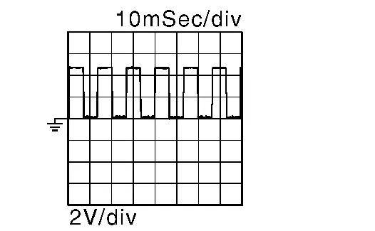
*: When the power consumption control of driver seat control unit is in wake-up state.
Is the inspection result normal?
YES>>Replace driver seat control unit. Refer to Removal and Installation.
NO>>GO TO 2.
CHECK SLIDING SENSOR SIGNAL CIRCUIT (OPEN)
-
Ignition switch OFF.
-
Disconnect driver seat control unit connector and sliding motor LH connector.
-
Check continuity between driver seat control unit harness connector and sliding motor LH harness connector.
Driver seat control unit Sliding motor LH Continuity Connector Terminal Connector Terminal B213 35 B216 3 Yes
Is the inspection result normal?
YES>>GO TO 3.
NO>>Repair the harness or connector.
CHECK SLIDING SENSOR SIGNAL CIRCUIT (SHORT TO GROUND)
Check continuity between driver seat control unit harness connector and ground.
| Driver seat control unit | (—) | Continuity | |
|---|---|---|---|
| Connector | Terminal | ||
| B213 | 35 | Ground | No |
Is the inspection result normal?
YES>>GO TO 4.
NO>>Repair the harness or connector.
CHECK SLIDING SENSOR POWER SUPPLY VOLTAGE
-
Connect driver seat control unit connector.
-
Check voltage between sliding motor LH harness connector and ground.
(+) (-) Voltage
(Approx.)Sliding motor LH Connector Terminal B216 4 Ground Battery voltage
Is the inspection result normal?
YES>>GO TO 7.
NO>>GO TO 5.
CHECK SLIDING SENSOR POWER SUPPLY CIRCUIT (OPEN)
-
Disconnect driver seat control unit connector.
-
Check continuity between sliding motor LH harness connector and driver seat control unit harness connector.
Sliding motor LH Driver seat control unit Continuity Connector Terminal Connector Terminal B216 4 B213 34 Yes
Is the inspection result normal?
YES>>GO TO 6.
NO>>Repair the harness or connector.
CHECK SLIDING SENSOR POWER SUPPLY CIRCUIT (SHORT TO GROUND)
Check continuity between sliding motor LH harness connector and ground.
| Sliding motor LH | (—) | Continuity | |
|---|---|---|---|
| Connector | Terminal | ||
| B216 | 4 | Ground | No |
Is the inspection result normal?
YES>>Replace driver seat control unit. Refer to Removal and Installation.
NO>>Repair the harness or connector.
CHECK SLIDING SENSOR GROUND CIRCUIT (OPEN)
-
Disconnect driver seat control unit connector.
-
Check continuity between sliding motor LH harness connector and driver seat control unit harness connector.
Sliding motor LH Driver seat control unit Continuity Connector Terminal Connector Terminal B216 2 B213 33 Yes
Is the inspection result normal?
YES>>Replace seat cushion frame. Refer to Disassembly and Assembly.
NO>>Repair the harness or connector.
Other materials:
B20a4-87 Headlamp (lh) Lin Communication
DTC Description
DTC DETECTION LOGIC DTC No.
CONSULT screen items
(Trouble diagnosis content) DTC detection condition
B20A4–87
Headlamp (LH) LIN communication
[Headlamp (left hand) local interconnect network communication]
[MISSING MESSAGE]
Diagnosis condition
Ignition switch ...
Dtc/circuit Diagnosis. B0028-1a Side A/b Module Rh
DTC Description
DTC DETECTION LOGIC DTC No.
CONSULT screen items
(Trouble diagnosis content) DTC Detection Condition
B0028-1A
SIDE A/B MODULE RH
(Right Side Airbag Deployment Control)
Diagnosis condition
When ignition switch is ON.
Signal (terminal)
Front side air bag modu ...
Charge Air Cooler
Exploded View
Charge air cooler
Charge air cooler Bracket 1
Turbocharger boost sensor (with intake air temperature sensor 2)
O-ring
Electronic throttle control actuator gasket
Charge air cooler Bracket 2
Air inlet hose
To r ...