Nissan Rogue (T33) 2021-Present Service Manual: Dtc/circuit Diagnosis :: B2436-12 Spindle Motor Lh
DTC Description
DTC DETECTION LOGIC
| DTC No. |
CONSULT screen items (Trouble diagnosis content) | DTC Detection Condition | |
|---|---|---|---|
| B2436-12 |
Spindle motor LH (Spindle motor left hand) |
Diagnosis condition | All times |
| Signal (terminal) | Spindle motor LH signal | ||
| Threshold | When automatic back door control unit detect power short of spindle motor LH circuit | ||
| Diagnosis delay time | 1 second or less | ||
POSSIBLE CAUSE
-
Harness or connector (spindle motor LH circuit is power short)
-
Automatic back door control unit
-
Spindle unit LH
FAIL-SAFE
Inhibit automatic back door system (only operate back door closure function)
DTC CONFIRMATION PROCEDURE
DTC CONFIRMATION
 CONSULT
-
Ignition switch ON.
-
Select âSelf diagnosis resultâ mode of âAUTOMATIC BACK DOORâ.
Is DTC detected?
YES>>Refer to DTC Diagnosis Procedure.
NO-1>>To check malfunction symptom before repair: Refer to Intermittent Incident.
NO-2>>Confirmation after repair: Inspection End.
DTC Diagnosis Procedure
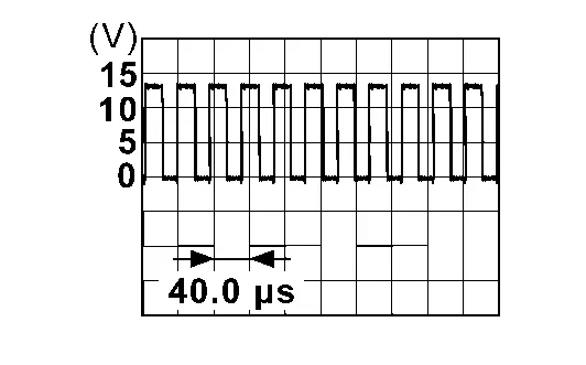
CHECK SPINDLE MOTOR INPUT SIGNAL
Check signal between spindle unit LH harness connector and ground using oscilloscope.
| (+) | (â) | Condition |
Signal (Reference value) (Approx.) | ||
|---|---|---|---|---|---|
| Spindle unit LH | |||||
| Connector | Terminal | ||||
| B95 | 1 | Ground | Back door | Auto open operation |
|
| Auto close operation | 0 â 1 V | ||||
| 7 | Auto close operation |
|
|||
| Auto open operation | 0 â 1 V | ||||
Is the inspection result normal?
YES>>Replace automatic back door control unit. Refer to Removal and Installation.
NO>>GO TO 2.
CHECK SPINDLE MOTOR CIRCUIT
-
Disconnect automatic back door control unit connector and spindle unit LH connector.
-
Check voltage between automatic back door control unit harness connector and ground.
Automatic back door control unit â Voltage
(Approx.)Connector Terminal B56 38 Ground 0 V 39
Is the inspection result normal?
YES>>Replace spindle unit LH. Refer to Removal and Installation.
NO>>Repair or replace harness.
Other materials:
Basic Inspection. Configuration (air Bag Diagnosis Sensor Unit)
Description
Vehicle specification needs to be written with CONSULT because it is
not written after replacing the air bag diagnosis sensor unit.The
configuration requires network connection. CONSULT connects to network
and then it downloads the configuration data from the server. Then
CONSUL ...
Drivetrain Can Communication 2 Circuit
Diagnosis Procedure
CHECK NETWORK DIAGNOSIS
Check the "Network diagnosis" results from CONSULT to see that the diagnostic CAN communication circuit have no malfunction.
Are the diagnostic CAN communication circuit normal?
YES>>
GO TO 2.
NO>>
Check and repair diagnostic CAN commu ...
SystÃĻme temporairement indisponible
Lorsque le tÃĐmoin d'avertissement de dÃĐsactivation du systÃĻme de commande dynamique du vÃĐhicule (VDC) se dÃĐsactive sur le Nissan Rogue, le tÃĐmoin d'avertissement de dÃĐsactivation du systÃĻme de freinage automatique arriÃĻre (RAB) s'allume afin d'informer le conducteur que l'assistance au frei ...